5G distributed network architecture communication tower erecting device
A distributed network and communication tower technology, applied in the field of 5G distributed network architecture communication tower erection device, can solve the problems of non-reusable tower body, high construction cost, difficult adjustment of communication tower angle and height, etc., and achieve highly flexible adjustment , high practicability, and the effect of improving practicability
- Summary
- Abstract
- Description
- Claims
- Application Information
AI Technical Summary
Problems solved by technology
Method used
Image
Examples
Embodiment 1
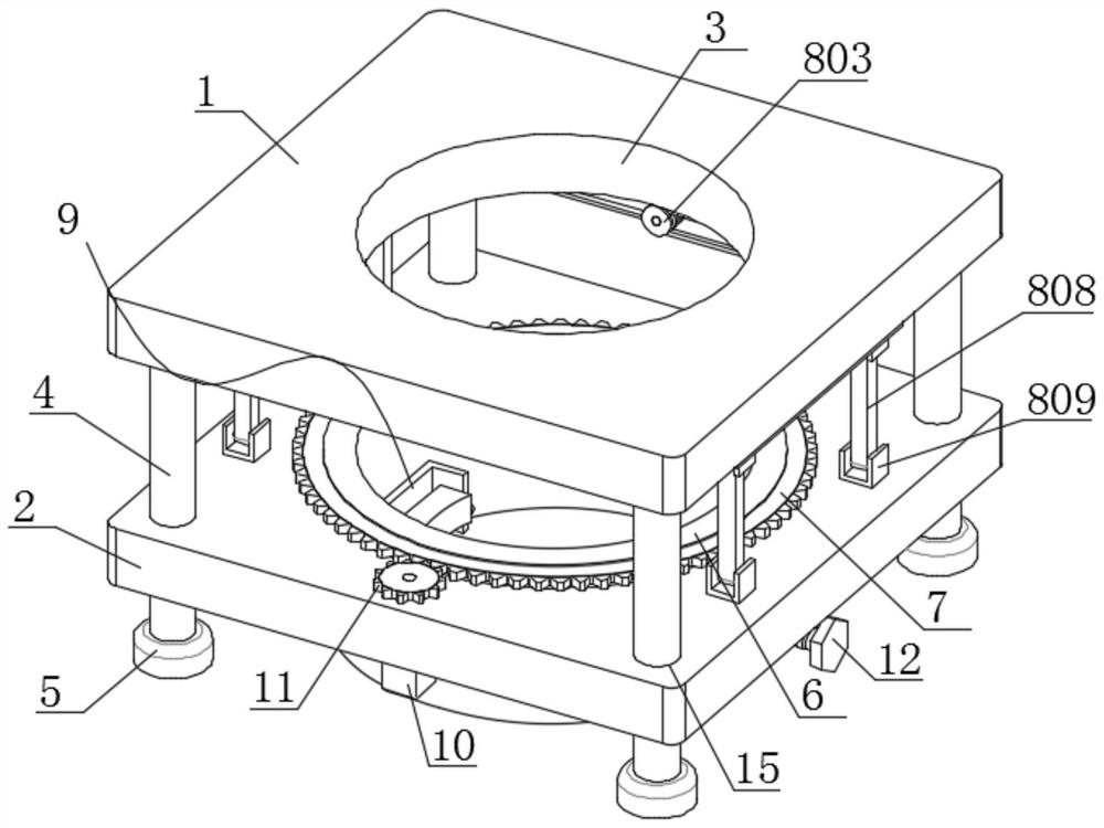
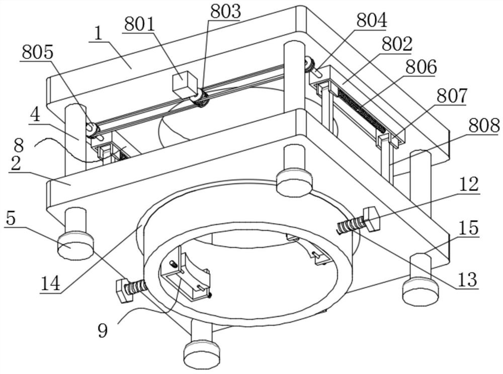
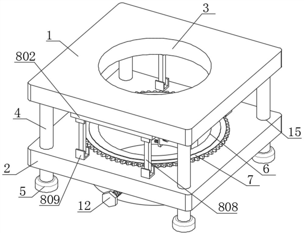
[0034] Such as Figure 1-6 A 5G distributed network architecture communication tower erection device shown includes a top plate 1 and a bottom plate 2. The inside of the top plate 1 is provided with a through hole 3. The bottom surface of the top plate 1 is fixedly connected with two sets of symmetrical support rods 4. The top plate 1 The bottom surface of the base plate is provided with a height-adjusting mechanism 8, and the inside of the bottom plate 2 is fixedly inlaid with a bearing 14, and the inner ring of the bearing 14 is fixedly connected with an annular block 6, and the inside of the annular block 6 is fixedly inlaid with two groups of symmetrical nuts 16, two nuts The inside of 16 is threadedly connected with a one-way screw rod 13, and one end of the two one-way screw rods 13 close to each other is provided with a clamping mechanism 9, and the two clamping mechanisms 9 all include a connecting block 901, and the two connecting blocks 901 are far away from each othe...
Embodiment 2
[0036] Embodiment 2: Embodiment 2 is a further improvement to Embodiment 1.
[0037] Such as Figure 1-6 A 5G distributed network architecture communication tower erection device shown includes a top plate 1 and a bottom plate 2. The inside of the top plate 1 is provided with a through hole 3. The bottom surface of the top plate 1 is fixedly connected with two sets of symmetrical support rods 4. The top plate 1 The height adjustment mechanism 8 is provided on the bottom surface of the bottom surface. The height adjustment mechanism 8 includes a forward and reverse motor 801 and two adjustment plates 802. On the bottom surface, the output shaft of the reversing motor 801 is fixedly connected with two driving wheels 803, the outer surfaces of the two driving wheels 803 are provided with belts 810, and the insides of the two adjusting plates 802 are connected with a two-way screw 804 in rotation. One end of two-way screw 804 close to the forward and reverse motor 801 runs throug...
Embodiment 3
[0039] Embodiment 3: Embodiment 3 is a further improvement to Embodiment 1;
[0040] Such as Figure 1-6 A 5G distributed network architecture communication tower erection device shown includes a top plate 1 and a bottom plate 2. The inside of the top plate 1 is provided with a through hole 3. The bottom surface of the top plate 1 is fixedly connected with two sets of symmetrical support rods 4. The top plate 1 The bottom surface of the base plate is provided with a height-adjusting mechanism 8, and the inside of the bottom plate 2 is fixedly inlaid with a bearing 14, and the inner ring of the bearing 14 is fixedly connected with an annular block 6, and the inside of the annular block 6 is fixedly inlaid with two groups of symmetrical nuts 16, two nuts The inside of 16 is threadedly connected with one-way screw rod 13, and one end of two one-way screw rods 13 close to each other is provided with clamping mechanism 9, and the top of the outer surface of ring block 6 is fixedly ...
PUM
 Abstract
Description
Claims
Application Information
 - R&D
- Intellectual Property
- Life Sciences
- Materials
- Tech Scout
- Unparalleled Data Quality
- Higher Quality Content
- 60% Fewer Hallucinations
Browse by: Latest US Patents, China's latest patents, Technical Efficacy Thesaurus, Application Domain, Technology Topic, Popular Technical Reports.
© 2025 PatSnap. All rights reserved.Legal|Privacy policy|Modern Slavery Act Transparency Statement|Sitemap|About US| Contact US: help@patsnap.com


