Anti-tearing pressure-reducing sliding chute buffering bed

A kind of impact bed, anti-tear technology, applied in conveyor objects, conveyors, non-rotating vibration suppression and other directions, can solve problems such as device failure and poor effect, and achieve the effect of improving service life and reducing high-frequency vibration

Inactive Publication Date: 2021-09-28
淮南市天力达工矿配件有限公司
View PDF1 Cites 1 Cited by
  • Summary
  • Abstract
  • Description
  • Claims
  • Application Information

AI Technical Summary

Problems solved by technology

The mine belt conveyor buffer bed has high universality. It can adjust the inclination angle and width of the side bed board according to the needs of use. It is easy to operate and easy to use, which greatly improves the flexibility of use. The side bed board can be adjusted by sliding the slide bar. The angle and the buffer strip are used to fully and effectively absorb the impact force when the material falls, and play a protective role. The extended bed board is connected with the side bed board through the insertion rod and the jack, and the width of the side bed board can be adjusted according to the needs of use, which is suitable for different materials. Buffering improves the universality. The above-mentioned buffer bed only has a buffering effect on its buffer strips. When facing the high-frequency vibration of the conveyor belt, the effect is not good, and it is easy to cause the failure of the entire device.

Method used


Image

  • Anti-tearing pressure-reducing sliding chute buffering bed
  • Anti-tearing pressure-reducing sliding chute buffering bed
  • Anti-tearing pressure-reducing sliding chute buffering bed

Examples


Embodiment Construction

[0028] The following will clearly and completely describe the technical solutions in the embodiments of the present invention with reference to the accompanying drawings in the embodiments of the present invention. Obviously, the described embodiments are only some, not all, embodiments of the present invention. Based on the embodiments of the present invention, all other embodiments obtained by persons of ordinary skill in the art without creative efforts fall within the protection scope of the present invention.

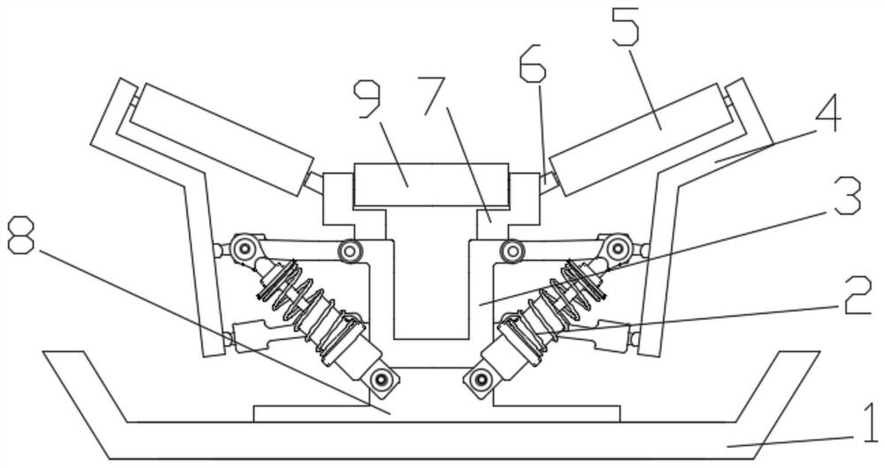
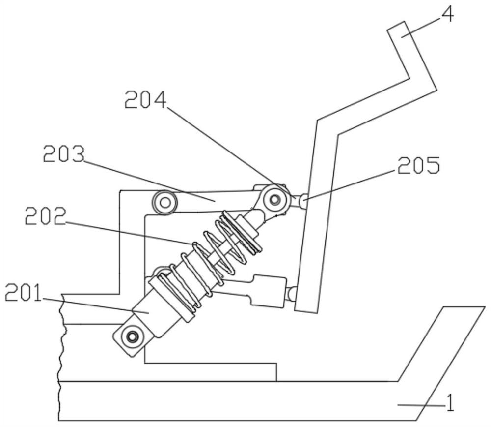
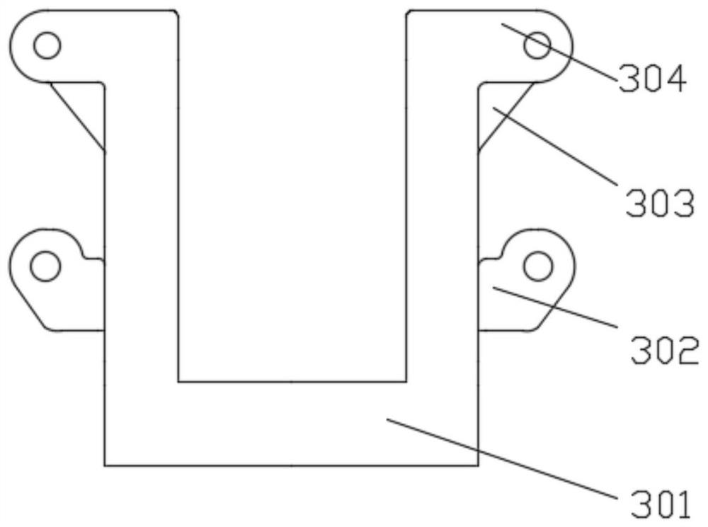
[0029] see Figure 1-6 As shown, the present invention is a kind of anti-tearing decompression chute buffer bed, including chassis 1, and the two sides of chassis 1 are arranged as groove shape, can effectively collect the cinder that falls, improve production environment, the chassis 1 The middle position of the top is fixedly equipped with a base two 8, and a main frame 3 is fixedly installed on one side of the top of the base two 8, buffer structures 2 are insta...


PUM


Abstract

The invention discloses an anti-tearing pressure-reducing sliding chute buffering bed which comprises a base plate. A second base is fixedly installed in the middle of the top of the base plate, a main frame is fixedly installed on one side of the top of the second base, buffering structures are installed on the two sides of the main frame, and a plurality of supporting frames are fixedly installed on the two sides of the top of the main frame. Second buffering wheels are installed between the two supporting frames, connecting frames are symmetrically installed on the two sides of the main frame, and first buffering wheels are installed between the supporting frames and the connecting frames. When the first buffering wheels are vibrated, first dampers acts to provide the restoring force for the connecting frames, and therefore the connecting frames can drive the first buffering wheels to quickly return to the initial position, and the vibration reducing and buffering effects are achieved. When the second buffering wheels are vibrated, second dampers bear the extrusion force, the restoring force of the second dampers pushes movable blocks to move along the tops of first bases, wedge-shaped blocks are extruded, and therefore the wedge-shaped blocks can move upwards, the vibration effects of the wedge-shaped blocks are balanced, the high-frequency vibration transmitted by a conveying belt is effectively reduced, and the service life of the buffering bed is prolonged.

Description

technical field [0001] The invention relates to the technical field of mining machinery, in particular to a tear-resistant decompression chute buffer bed. Background technique [0002] The buffer chute is a buffer bed or a buffer drag bed. It is generally composed of a slider and a supporting steel structure (other accessories). The slider is vulcanized by natural wear-resistant rubber. It is mainly used to absorb impact and reduce wear on the belt. , the support structure mainly plays the role of bearing the impact kinetic energy. The common models are flame retardant, ordinary, medium, heavy and super heavy. The current buffer beds use cushion pads instead of rollers. The buffer strips are mainly used for excellent high The elastic special rubber layer fully and effectively absorbs the vibration of the belt when the material is transported by the belt, but blindly using the buffer strip instead of the roller and ignoring the friction resistance of the buffer strip also has...

Claims


Application Information

Patent Timeline
Patent Type & Authority Applications(China)
IPC IPC(8): B65G15/60B65G39/02B65G39/12F16F15/06
CPCB65G15/60B65G39/02B65G39/12F16F15/06B65G2201/04
Inventor 张永
Owner 淮南市天力达工矿配件有限公司
Why Eureka
Try Eureka