Water storage tank water overflowing and supplementing system for elevator stowage
A technology of water replenishment system and water storage tank, which can be used in pipeline systems, gas/liquid distribution and storage, lifting equipment in mines, etc., and can solve problems such as inability to implement
- Summary
- Abstract
- Description
- Claims
- Application Information
AI Technical Summary
Problems solved by technology
Method used
Image

Examples
Embodiment Construction
[0036] The following will clearly and completely describe the technical solutions in the embodiments of the present invention with reference to the accompanying drawings in the embodiments of the present invention. Obviously, the described embodiments are only some, not all, embodiments of the present invention. Based on the embodiments of the present invention, all other embodiments obtained by persons of ordinary skill in the art without making creative efforts belong to the protection scope of the present invention.
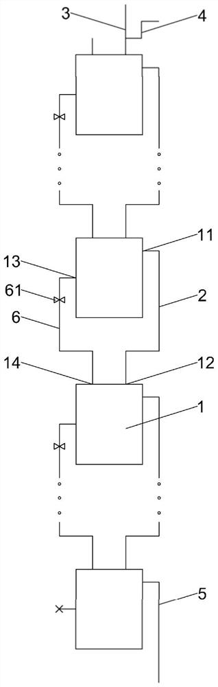
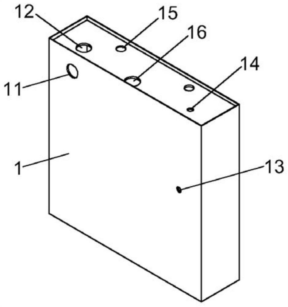
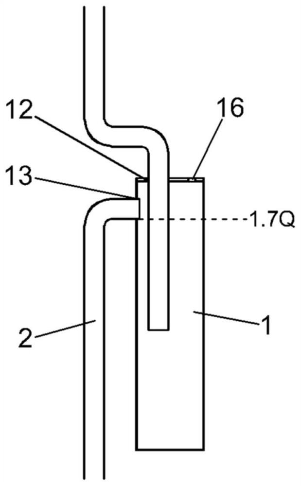
[0037] Such as Figure 1-4 As shown, a water storage tank overflow replenishment system for loading elevators includes a plurality of water storage tanks 1, and the water storage tanks 1 are arranged at the floor where the elevator stops in the elevator shaft, and are used for distributing water tanks for loading elevators. Heavy; the water storage tank 1 has an overflow outlet 11, an overflow inlet 12, a water replenishment outlet 13, a water replenishment in...
PUM
 Abstract
Description
Claims
Application Information
PatSnap Eureka turns technology decisions into work you can execute. Powered by our Innovation Knowledge Graph, it runs expert workflows across engineering, life sciences, materials and intellectual property. Get your review-ready output in minutes.


