Continuous firing mechanism of paintball gun

A technology of paintball guns and continuous firing, applied in the field of paintball guns, which can solve the problems of low gas utilization rate, poor precision, low initial velocity, etc., and achieve good shooting reliability, applicable range of use, and good timeliness of ammunition supply Effect

Active Publication Date: 2021-09-28
CHONGQING JIANSHE IND GRP
View PDF5 Cites 0 Cited by
  • Summary
  • Abstract
  • Description
  • Claims
  • Application Information

AI Technical Summary

Problems solved by technology

The gravitational feeding cycle of the bucket is only affected by the diameter of the projectile and the feeding angle. The current method to improve the timeliness of the bullet feeding from the bucket on the market is to install an electric drive mechanism. It can achieve relatively reliable bomb feeding, but because the radio frequency is too high, it will cause a series of problems such as low gas utilization rate, low muzzle velocity, and poor accuracy.

Method used


Image

  • Continuous firing mechanism of paintball gun
  • Continuous firing mechanism of paintball gun
  • Continuous firing mechanism of paintball gun

Examples


Embodiment Construction

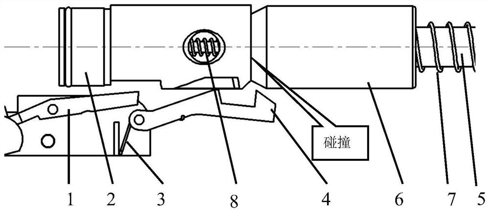
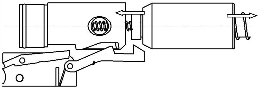
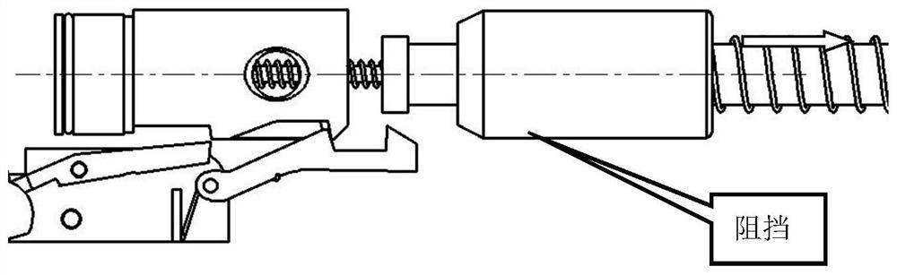
[0023] see Figure 1-Figure 4 , which is a paintball gun burst mechanism, including a stub 1, a hammer 2, and the hammer 2 is driven by a hammer spring 8 to return, and also includes a delay body 6, and the delay body 6 is slidably fitted on the On the recoil spring guide rod 5, and through the time delay body recoil spring 7 set on the recoil spring guide rod 5, the recoil is driven. The iron 4 is driven back and forth by the continuous firing stubbing spring 3, the lower end of the hammer 2 is provided with a bar-shaped groove, and the free end of the continuous firing stubbing iron 4 is provided with an upwardly protruding blocking part and a pressing part. A space is formed between the blocking part and the pressing part, which is used to make way for the lower part of the rear end of the hammer 2. The front end of the blocking part is provided with an inclined surface, which is used to cooperate with the rear end of the hammer 2 to press down and fire continuously. The fr...


PUM


Abstract

The invention discloses a continuous firing mechanism of a paintball gun. The ideal full-automatic continuous firing of the paintball gun is achieved. The continuous firing mechanism of the paintball gun comprises a sear, a driving hammer, the driving hammer drives counter-recoil through a driving hammer spring, the continuous firing mechanism of the paintball gun further comprises a delay body, the delay body is arranged on a counter-recoil spring guide rod in a sliding fit mode and drives counter-recoil through a delay body counter-recoil spring arranged on the counter-recoil spring guide rod in a sleeving mode, a running-firing sear is hinged to the sear, a continuous firing sear drives counter-recoil through a continuous firing sear spring, a strip-shaped groove is formed in the lower end of the driving hammer, the free end of the continuous firing sear is provided with a blocking part protruding upwards and a pressing part, a receding space is formed between the blocking part and the pressing part and used for receding the lower portion of the rear end of the driving hammer, the front end of the blocking part is provided with an inclined face used for being matched with the rear end of the driving hammer to press the free end of the continuous firing sear downwards, the rear end of the blocking part is provided with a limiting face used for being matched with the rear wall of the strip-shaped groove to limit the driving hammer, and the rear end of the pressing part is provided with the inclined surface which is used for being matched with the front end of the delay body to press the free end of the continuous firing sear downwards, so that the limiting of the driving hammer is relieved.

Description

technical field [0001] The invention relates to the technical field of paintball guns, in particular to a continuous firing mechanism of a paintball gun. Background technique [0002] At present, the mainstream non-electronically-controlled paintball guns on the market only have semi-automatic firing functions and do not have fully automatic bursting functions. The main reason for this is that the mainstream paintball guns all adopt the structure of open-bore standby and hopper feeding. Firearms that are ready to open have high radio frequency, while the paintball guns that are fed by hoppers only rely on gravity to fall to achieve projectile feeding. match, so fully automatic firing cannot be achieved. [0003] To solve the contradiction between the timeliness of bomb supply and the radio frequency mismatch, we can only greatly reduce the radio frequency or improve the timeliness of bomb supply. The period of gravity feeding of the hopper is only affected by the diameter...

Claims


Application Information

Patent Timeline
Patent Type & Authority Applications(China)
IPC IPC(8): F41B11/50F41B11/70
CPCF41B11/50F41B11/70
Inventor 彭璐谌炳军唐成刚袁凯朱应秋龚会黄宜民胡永勇沈潇武旭飞
Owner CHONGQING JIANSHE IND GRP
Why Eureka
Try Eureka