Device and simulation method for simulating the effect of high temperature heat-conducting components on fire extinguishing

A technology of heat conduction components and fire extinguishing devices, which can be applied to simulators for space navigation conditions, simulators, fire rescue, etc., and can solve problems such as hindering the foam coverage effect, foam not being able to cover oil products, and oil vapor re-ignition

Active Publication Date: 2022-07-08
CHINA UNIV OF MINING & TECH (BEIJING)
View PDF11 Cites 2 Cited by
  • Summary
  • Abstract
  • Description
  • Claims
  • Application Information

AI Technical Summary

Problems solved by technology

If there are exposed high-temperature heat-conducting components in the storage tank, the continuous downward heat transfer of the high-temperature heat-conducting components will cause the surrounding oil to boil, which will hinder the covering effect of the foam, resulting in the foam not being able to cover the oil and low fire extinguishing efficiency
In addition, after the fire is extinguished, the high-temperature heat-conducting components will continue to heat the oil, causing the oil to generate a large amount of oil vapor, which can easily lead to re-ignition of the oil vapor and make it difficult to extinguish the fire. This brings a huge challenge to the fire-fighting work of the fire brigade

Method used


Image

  • Device and simulation method for simulating the effect of high temperature heat-conducting components on fire extinguishing
  • Device and simulation method for simulating the effect of high temperature heat-conducting components on fire extinguishing
  • Device and simulation method for simulating the effect of high temperature heat-conducting components on fire extinguishing

Examples


Embodiment Construction

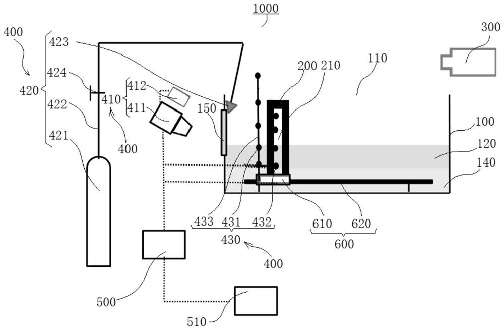
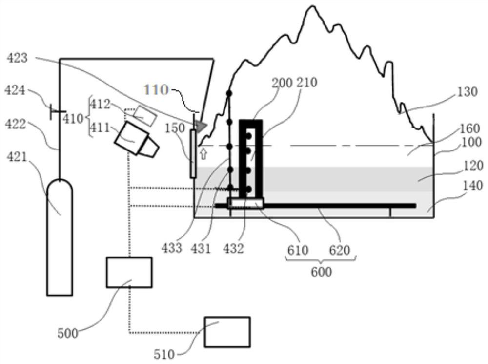
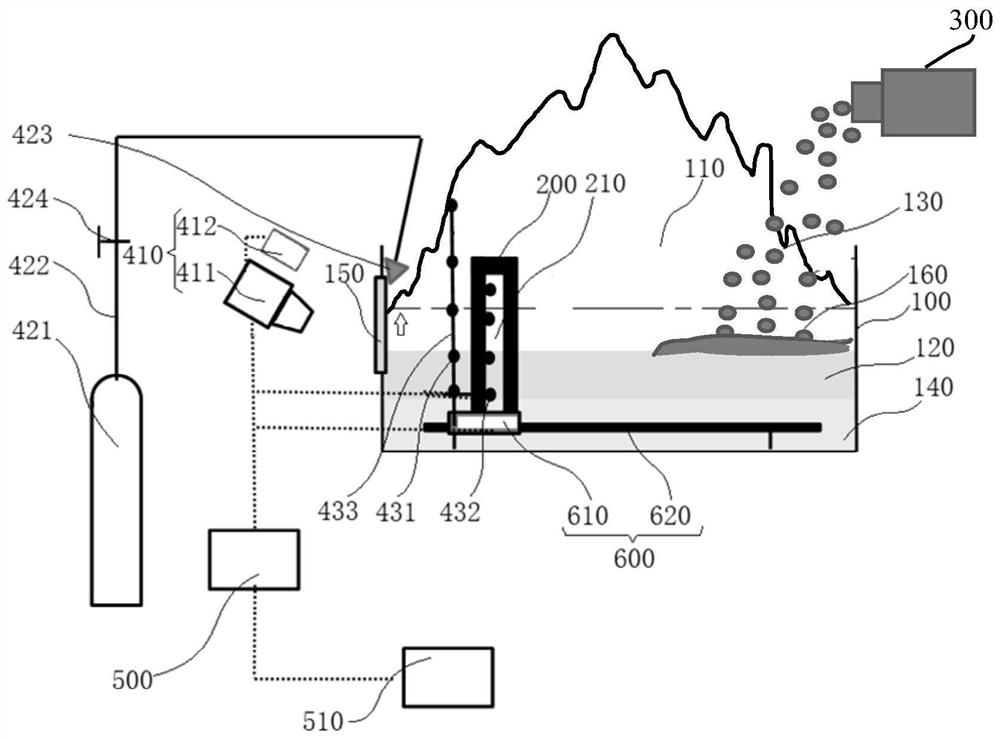
[0038] Embodiments of the present invention are described in detail below, examples of which are illustrated in the accompanying drawings, wherein the same or similar reference numerals refer to the same or similar elements or elements having the same or similar functions throughout. The embodiments described below with reference to the accompanying drawings are exemplary, only used to explain the present invention, and should not be construed as a limitation of the present invention.

[0039] In the description of the present invention, it should be understood that the terms "upper", "lower", "front", "rear", "vertical", "horizontal", "top", "bottom", "inner", The orientation or positional relationship indicated by "outside", etc. is based on the orientation or positional relationship shown in the drawings, which is only for the convenience of describing the present invention and simplifying the description, rather than indicating or implying that the indicated device or eleme...


PUM


Abstract

The invention discloses a device and a simulation method for simulating the influence of high-temperature heat-conducting components on fire extinguishing, comprising: a container, a heat-conducting component, a fire-extinguishing device and a monitoring device. One end of the container is open, and the container carries a layer of combustible liquid. The layer of combustible liquid is combustible in the air, and a flame is formed when the layer of combustible liquid is burned. The heat-conducting member is arranged in the container, a portion of the heat-conducting member is located in the combustible liquid layer, and a portion of the heat-conducting member extends to the flame. The fire extinguishing device is used to extinguish the flame in the container. The monitoring device is used to monitor the status information in the combustible liquid layer and / or the heat conducting member. In the device of the embodiment of the present invention, the heat-conducting member heated by the flame can simulate the high-temperature heat-conducting member at the fire scene, and the monitoring device can monitor the combustion and fire-extinguishing conditions of the combustible liquid layer in real time, and can also monitor the physical state of the heat-conducting member to reproduce the existence of high temperature The influence of heat-conducting components on the fire and extinguishing process of storage tanks can provide rescue guidance.

Description

technical field [0001] The invention belongs to the technical field of fire simulation testing of storage tanks, in particular to a device and a simulation method for simulating the influence of high-temperature heat-conducting components on fire extinguishing. Background technique [0002] The large floating roof tank is composed of floating trays, side walls, escalators and other devices. A large amount of oil is stored in the storage tank. The floating tray can isolate the oil from the atmosphere, thereby greatly reducing the evaporation of the oil during storage. Losses, reduce air pollution, and reduce the risk of oil fires and explosions, reducing the burning area in the event of a fire. [0003] However, after a fire, some of the heat-conducting components are exposed to the combustion flame in many cases, and the other part is submerged in the oil, such as the escalator connecting the floating plate. At this time, the flame continuously heats the exposed part, causi...

Claims


Application Information

Patent Timeline
Patent Type & Authority Patents(China)
IPC IPC(8): G09B9/00A62C37/50A62C3/06
CPCG09B9/00A62C99/0081A62C37/50A62C3/065
Inventor 赵金龙章翔李昭乾李信江
Owner CHINA UNIV OF MINING & TECH (BEIJING)
Why Eureka
Try Eureka