
Transmission conductor holding structure of electric connector

A technology of electrical connectors and transmission conductors, which is applied to the parts, connections, circuits, etc. of the connection device, which can solve the problems of loosening of the holding structure and the insulating colloid, insufficient bonding strength, etc., and achieve the effect of stabilizing the strength of the male-female butt joint

Pending Publication Date: 2021-09-28
ASSEM TECH
View PDF8 Cites 0 Cited by
  • Summary
  • Abstract
  • Description
  • Claims
  • Application Information

AI Technical Summary

Problems solved by technology

[0005] First, the bonding strength between the holding structure and the insulating colloid is insufficient, resulting in the loosening of the holding structure and the insulating colloid when the plug connector is disassembled and separated.
[0006] Second, the stronger the holding structure helps the male-female butt joint strength, the higher the possibility that the holding structure of the socket connector will be pulled out when the plug connector is disassembled and separated, and it is difficult to obtain a balance between the bonding strength and the butt joint strength. balance

Method used


Image

  • Transmission conductor holding structure of electric connector
  • Transmission conductor holding structure of electric connector
  • Transmission conductor holding structure of electric connector

Examples


Embodiment Construction

[0023] In order to achieve the above-mentioned purpose and effect, the technical means and structures adopted by the present invention are now described in detail with reference to the preferred embodiments of the present invention with reference to the accompanying drawings. The features and functions are as follows for a complete understanding.

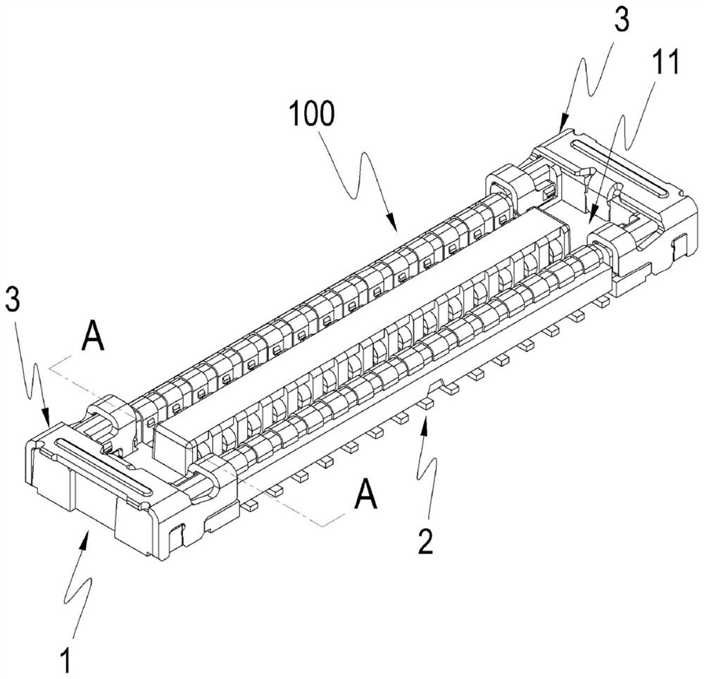
[0024] see Figures 1 to 9 As shown, the transmission conductor holding structure of the electrical connector of the present invention can be clearly seen from the figure, and the electrical connector 100 is a board-to-board connector (Borad To Board, BTB connector), including:

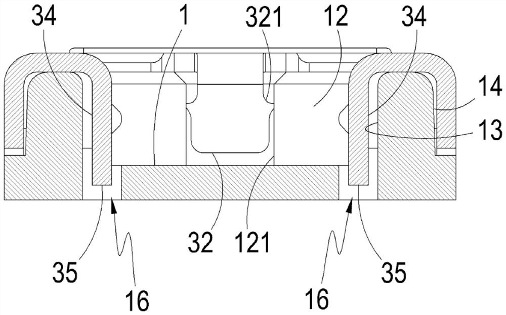
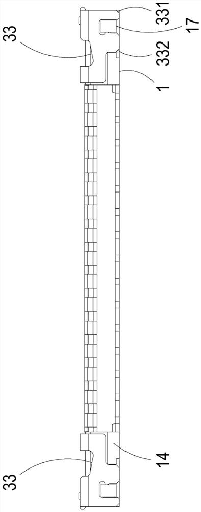
[0025] A female seat colloid 1, the female seat colloid 1 is respectively formed with a receiving groove 11 at the opposite ends of the arrangement direction of the female seat terminal 2 below, and each of the receiving grooves 11 includes an inner end surface 12, two forming Side end surfaces 13 on both sides of the inner end surface 12, two outer surface...


PUM


Abstract

The invention discloses a transmission conductor holding structure of an electric connector. The structure comprises a female seat colloid, a plurality of female seat terminals, two female seat holding structures located on different sides of the female seat terminals, two end plate parts defined on the female seat holding structures, two end buckling arms formed on one sides of the end plate parts in a bending manner, a plurality of side plate parts formed at different ends of the end plate parts in a bending manner, a plurality of clamping plate parts adjacent to one sides of the female seat terminals, a plurality of convex foot parts which are formed by extending from the end of the clamping plate part, a plurality of locking arms which are formed on one side of the clamping plate part, a plurality of clamping parts which are formed on the locking arms in a protruding manner, and a plurality of limiting holes which are formed in the female seat colloid. The end plate parts, the side plate parts, the end buckling arms, the clamping plate parts and the locking arms are respectively arranged from a plurality of faces of the female seat colloid to really fix the female seat holding structure, and the convex foot parts are inserted into the limiting holes, so that the female seat holding structure and the female seat colloid are prevented from being loosened or separated when the male connector is pulled out.

Description

technical field [0001] The present invention provides a transmission conductor holding structure of an electrical connector, especially a transmission conductor holding structure of an electrical connector that has good bonding strength to colloids, strong stability of male-female docking, and is not easy to be loosened and damaged during separation. . Background technique [0002] The board-to-board connector is used to connect different circuit boards, and has a socket connector and a plug connector to be respectively installed on different circuit boards, thereby connecting the circuit boards to each other. The holding structure at both ends of the socket connector, in addition to providing a certain degree of protective effect of the insulating colloid, is mainly to strengthen the locking effect on the plug connector, so as to maintain the fitting state between the plug connector and the socket connector. Purpose. [0003] On mobile devices such as smartphones, the siz...

Claims


Application Information

Patent Timeline
Patent Type & Authority Applications(China)
IPC IPC(8): H01R12/71H01R13/422H01R13/502H01R13/627
CPCH01R12/716H01R13/502H01R13/422H01R13/627
Inventor 林宜修李振隆
Owner ASSEM TECH
Learn More