Self-adaptive angle accurate positioning and clamping device for adjustable blade

A technology with precise angle and clamping device, which is applied in the direction of positioning device, clamping, supporting, etc., can solve the problems of easy deformation of parts, complex blade shape, difficulty in clamping of blade surface, and difficulty in positioning other parts, and achieve reliable pressure. The effect of tight force, fast and precise positioning

Pending Publication Date: 2021-10-01
CHENGDU HOLY AVIATION SCI & TECH CO LTD
View PDF1 Cites 1 Cited by
  • Summary
  • Abstract
  • Description
  • Claims
  • Application Information

AI Technical Summary

Problems solved by technology

[0005] The main purpose of the present invention is to provide an adjustable blade self-adaptive angle precise positioning and clamping device, aiming to solve the problem of blade surface clamping and positioning in the prior art due to factors such as complex blade shape and easy deformation of parts. Technical issues where machining other parts becomes very difficult

Method used


Image

  • Self-adaptive angle accurate positioning and clamping device for adjustable blade
  • Self-adaptive angle accurate positioning and clamping device for adjustable blade
  • Self-adaptive angle accurate positioning and clamping device for adjustable blade

Examples


Embodiment 1

[0033] In order to realize the positioning and clamping of the fan blades of the aero-engine, the following embodiments are proposed:

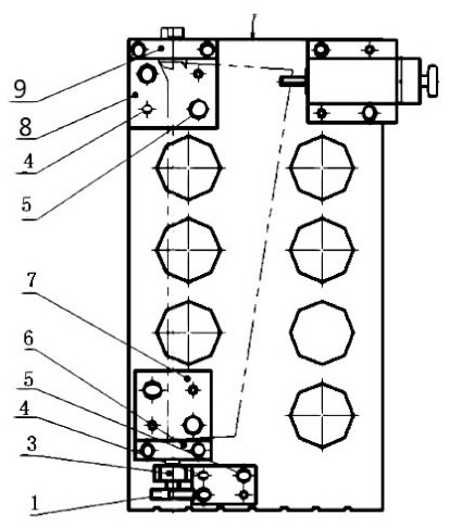
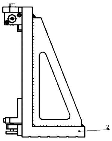
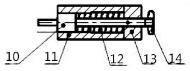
[0034] Such as figure 1 , figure 2 , image 3 with Figure 8 As shown, in this embodiment, an adjustable fan blade self-adaptive angle precise positioning and clamping device is proposed, including a tightening bolt 1, a clamp body 2, a bracket 3, a small end positioning block 7, a large end positioning block 8 and Orienter 11; the clamping bolt 1 is fixed on the lower left side of the clamp body 2 through the interference fit of the positioning pin and the compression screw; the upper end of the clamping bolt 1 is connected to the bracket 3, and the bracket 3 is fixedly arranged on the clamp body 2 Above; the small end positioning block 7 is set on the upper end of the bracket 3 for connecting and fixing one end of the fan blade; the big end positioning block 8 is set on the upper left of the clamp body 2 for connecting and fixing the top...

Embodiment 2

[0055] In order to realize the positioning and clamping of the turboprop blade of the aero-engine, the following embodiments are proposed:

[0056] Such as figure 1 , figure 2 , image 3 with Figure 8 As shown, in this embodiment, an adjustable turboprop blade self-adaptive angle precise positioning clamping device is proposed, including a tightening bolt 1, a clamp body 2, a bracket 3, a small end positioning block 7, and a large end positioning block 8 and an orienter 11; the jacking bolt 1 is fixed on the lower left side of the clamp body 2 through an interference fit of a positioning pin and a compression screw; the upper end of the jacking bolt 1 is connected to a bracket 3, and the bracket 3 is fixedly arranged on the clamp body 2; the small end positioning block 7 is arranged on the upper end of the bracket 3 for connecting and fixing one end of the blade; the large end positioning block 8 is arranged on the upper left of the clamp body 2 for connecting and fixing ...


PUM


Abstract

The invention discloses a self-adaptive angle accurate positioning and clamping device for an adjustable blade. The self-adaptive angle accurate positioning and clamping device comprises a puller bolt (1), a clamp body (2), a bracket (3), a small-end positioning block (7), a large-end positioning block (8) and an orientator (11), wherein the puller bolt (1) is fixed to the lower left portion of the clamp body (2) through interference fit of a positioning pin and a compression screw; the upper end of the puller bolt (1) is connected with the bracket (3); the small-end positioning block (7) is arranged at the upper end of the bracket (3); the large-end positioning block (8) is arranged on the upper left portion of the clamp body (2); the orientator (11) is arranged on the upper right portion of the clamp body (2), and a orienting chuck (10) horizontally moves and circumferentially rotates under the action of a spring (12) and is matched with the small-end positioning block (7) and the large-end positioning block (8) to automatically determine the position of the blade. The orienting chuck (10) of the device adopts a symmetrical V-shaped structure, can adapt to the thickness change of a blade profile and the deformation of the blade profile, and can realize accurate positioning through the orientator.

Description

technical field [0001] The invention relates to the field of clamping and positioning technology, in particular to an adjustable blade self-adaptive angle precise positioning clamping device. Background technique [0002] Aviation blades are a very important type of aero-engine parts. The shape of the blade is often a complex and irregular surface, and its precision requirements are relatively high, so higher requirements are put forward for its clamping and measurement. At present, a three-coordinate measuring machine is commonly used to measure it, and the aviation blade is placed on the three-coordinate measuring machine. on the measurement platform. However, the three-coordinate measuring machine has strict requirements on the detection environment, and requires professionals to operate, the detection efficiency is low, and the detection cost is high. [0003] In the utility model patent application document with the application number CN201920421243.0, a clamp for cla...

Claims


Application Information

Patent Timeline
Patent Type & Authority Applications(China)
IPC IPC(8): B23Q3/06
CPCB23Q3/062
Inventor 刘尚明刘波刘遵友
Owner CHENGDU HOLY AVIATION SCI & TECH CO LTD
Why Eureka
Try Eureka