
Automatic clamping device for cylindrical grinder

A technology of automatic clamping and clamping devices, which is applied in the direction of grinding drive devices, grinding machine parts, grinding machines, etc., can solve problems such as low processing efficiency and insufficient safety, and achieve improved processing efficiency, avoiding injuries, and safety performance high effect

Pending Publication Date: 2021-10-01
ANHUI LICHENG MACHINERY EQUIP
View PDF0 Cites 0 Cited by
  • Summary
  • Abstract
  • Description
  • Claims
  • Application Information

AI Technical Summary

Problems solved by technology

[0003] Aiming at the defects and deficiencies in the prior art, the present invention proposes an automatic clamping device for external round grinding machines, which solves the problem of low processing efficiency and insufficient safety caused by the cooperation of the top and the driving ring in machine tool processing. Improve the efficiency of machine tool processing operations, making machine tool processing operations safer and more reliable

Method used


Image

  • Automatic clamping device for cylindrical grinder
  • Automatic clamping device for cylindrical grinder
  • Automatic clamping device for cylindrical grinder

Examples


Embodiment Construction

[0022] Specific embodiments of the present invention will be described in detail below in conjunction with the accompanying drawings.

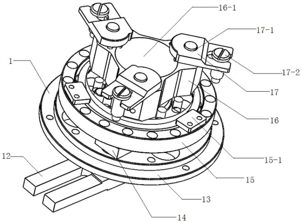
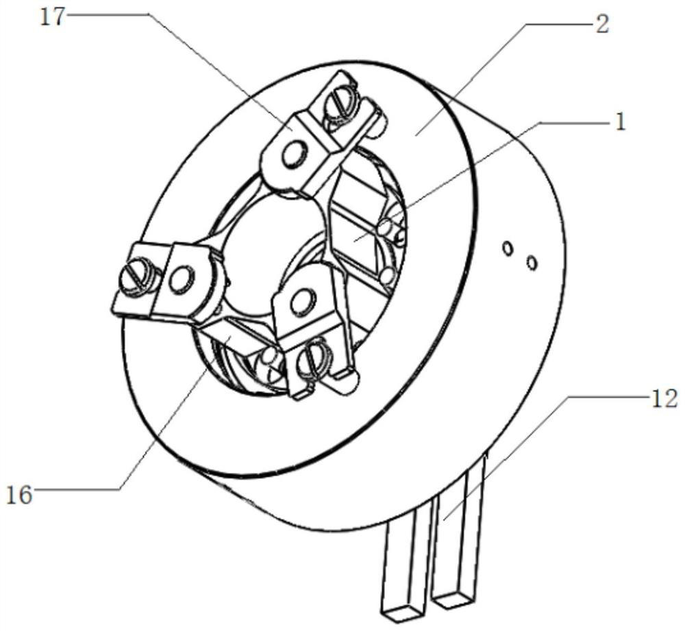
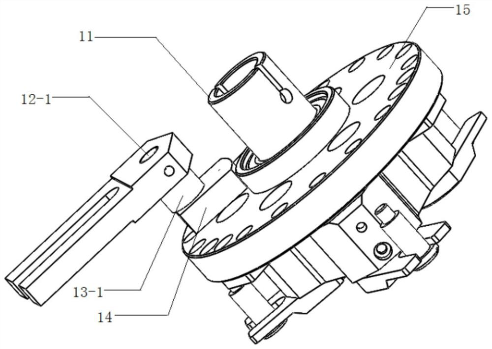
[0023] Such as Figure 1~5 As shown, an automatic clamping device for an external round grinding machine includes a clamping device main body 1 and a gland 2, the top end of the clamping device main body 1 is covered with a gland 2, and the clamping device main body 1 includes a fixed shaft 11, Limiting block 12, mounting seat 13, limiting block mounting plate 14, fixed seat 15, clamping claw mounting seat 16, clamping claw 17, the outer side of fixed shaft 11 is covered with mounting seat 13, the fixed shaft below mounting seat 13 11 is provided with a fixed ring 18, and the mounting seat 13 is provided with a through hole, and the rotating shaft 12-1 passes through the through hole to fix the limiting block 12, the mounting seat 13, and the limiting block mounting plate 14 together, and the mounting seat 13 The bottom is provided with a lim...


PUM


Abstract

The invention relates to an automatic clamping device for a cylindrical grinder, and belongs to the technical field of machine tools. The automatic clamping device for the cylindrical grinder comprises a clamping device body and a gland. The clamping device body comprises a fixing shaft, a limiting block, a mounting seat, a limiting block mounting plate, a fixing seat, a clamping claw mounting seat and a plurality of clamping claws, wherein the fixing shaft is sleeved with the mounting seat, the limiting block is arranged at the bottom of the mounting seat, the limiting block mounting plate is arranged at the top of the mounting seat, the fixing seat is arranged at the top of the limiting block mounting plate, the clamping claw mounting seat is arranged at the top of the fixing seat, the clamping claw mounting seat is provided with the multiple clamping claws, the clamping device main body is covered with a gland, the heads of the clamping claws are hinged to the top of the clamping claw mounting seat, and the tails of the clamping claws are mounted at the top of the gland. The problems that the machining efficiency is low and the machining is not safe enough due to the fact that a center and a driving ring are used in cooperation in machine tool machining are solved, the efficiency of machine tool machining is improved, and the machine tool machining becomes safer and more reliable.

Description

technical field [0001] The invention relates to the technical field of machine tools, in particular to an automatic clamping device for an external round grinding machine. Background technique [0002] Such as Figure 6 As shown, in the process of machine tool processing workpieces, the joint use of the top and the driving ring is generally used to fix the workpiece 5 for processing, especially on the external round grinding machine; One end of the workpiece is manually operated to drive the ring to clamp the side of the workpiece 5 for processing, thereby fixing the workpiece 5 for processing; although this method of fixing the workpiece 5 can also be used for processing the workpiece, the work efficiency is low And not safe enough. Contents of the invention [0003] Aiming at the defects and deficiencies in the prior art, the present invention proposes an automatic clamping device for external round grinding machines, which solves the problem of low processing efficienc...

Claims


Application Information

Patent Timeline
IPC IPC(8): B24B41/06B24B47/00B24B5/04
CPCB24B41/067B24B5/04B24B47/00
Inventor 周庆成金平金刘生王高舒志国董伟何英明
Owner ANHUI LICHENG MACHINERY EQUIP
Learn More