A high-temperature rotary heating device for bolt surface treatment

A technology of surface treatment and rotating heating, which is applied in metal material coating process, coating, solid-state diffusion coating, etc., can solve the problems of polluting the working environment, endangering the health and safety of workers, and the dust of multi-element alloy co-infiltration agent, etc. To achieve the effect of ensuring health and safety, simple operation mode and small footprint

Inactive Publication Date: 2018-01-12
WUHU ZHONGYUAN COMPOSITE NEW MATERIALS CO LTD
View PDF6 Cites 0 Cited by
  • Summary
  • Abstract
  • Description
  • Claims
  • Application Information

AI Technical Summary

Problems solved by technology

[0004] In the prior art, when bolts for construction engineering are subjected to multi-component alloy co-infiltration treatment, it is usually necessary to mix the bolts with multi-component alloy co-infiltration agent and fill them into the co-infiltration furnace, and then close the co-infiltration furnace for rotary heating co-infiltration treatment. After the heating co-infiltration treatment is completed, the bolts mixed with the co-infiltration agent are sorted out. The disadvantage of the above operation process is that the bolts located at the axis of the co-infiltration furnace are not in sufficient contact with the multi-component alloy infiltration agent. The effect of multi-component alloy co-infiltration treatment of bolts is not good or the time of multi-component alloy co-infiltration treatment needs to be prolonged; in addition, when the bolts mixed with co-infiltration agent are placed in the working environment for natural cooling and sorting operations, multi-component alloy co-infiltration Penetrating agent dust will drift away, polluting the working environment and endangering the health and safety of workers

Method used


Image

  • A high-temperature rotary heating device for bolt surface treatment
  • A high-temperature rotary heating device for bolt surface treatment
  • A high-temperature rotary heating device for bolt surface treatment

Examples


Embodiment Construction

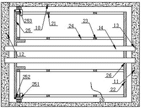
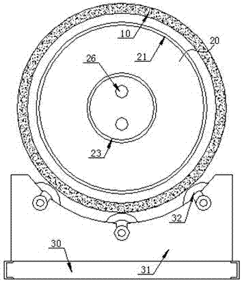
[0020] refer to Figure 1 to Figure 4 , Figure 1 to Figure 4 It is a structural schematic diagram of a specific embodiment of the present invention.

[0021] Such as Figures 1 to 4 As shown, a high-temperature rotary heating device for bolt surface treatment includes a rotary heating tank 10, which is a closed cylindrical structure and includes a heating tank bottom wall 11 and a heating tank cover 12; Car 30, the heating tank rotating car 30 is provided with a rotating support frame 31 along the axial ends of the rotating heating tank 10, and the top of the rotating support frame 31 is provided with several circular arc-shaped The two axial ends of the rotating heating tank 10 are placed on the support rollers 32 parallel to each other.

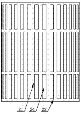
[0022] The rotary heating tank 10 is provided with a centralized processing cage 20, the centralized processing cage 20 includes a circular rolling outer wall 21 of a tubular structure, one axial end of the circular rolling outer wall 2...


PUM


Abstract

The invention discloses a high-temperature rotation heating device for bolt surface processing. The high-temperature rotation heating device for the bolt surface processing comprises a rotation heating tank, wherein the rotation heating tank is of a closed cylindrical structure and comprises a heating tank bottom wall and a heating tank seal cover. A centralized processing cage is arranged in the rotation heating tank and comprises a round rolling outer side wall of a tubular structure, a round rolling bottom wall, a round rolling inner side wall and a round rolling seal cover; a plurality of hollowed permeating agent permeable holes are formed in the round rolling inner side wall and the round rolling outer side wall; hollow synchronous rolling limiting holes are formed in the round rolling seal cover and the round rolling bottom wall correspondingly and formed in the inner side of the round rolling inner side wall; synchronous rolling fixation holes are formed in the heating tank bottom wall and the heating tank seal cover; and the centralized processing cage further comprises synchronous rolling connection rods with the two ends located inside the synchronous rolling fixation holes and the middle portions penetrating through the synchronous rolling limiting holes.

Description

technical field [0001] The invention relates to the technical field of bolt surface treatment equipment for construction engineering, in particular to a high-temperature rotary heating equipment for bolt surface treatment. Background technique [0002] Bolts used in construction projects in reinforced concrete structures such as bridges are prone to corrosion and damage to concrete structures due to long-term exposure to various corrosion-causing factors such as freezing damage, chemical corrosion, steel corrosion, and alkali-aggregate reaction; especially due to humidity The effect of carbon dioxide, temperature and carbon dioxide will cause the carbonization of concrete, and the effect of corrosive media such as oxygen, sulfur dioxide and chlorine will further aggravate the corrosion and damage of the concrete structure. In order to improve the corrosion resistance of bolts used in construction engineering, multi-element alloy co-infiltration anti-corrosion treatment measu...

Claims


Application Information

Patent Timeline
Patent Type & Authority Patents(China)
IPC IPC(8): C23C10/52
CPCC23C10/52
Inventor 晋华明
Owner WUHU ZHONGYUAN COMPOSITE NEW MATERIALS CO LTD
Why Eureka
Try Eureka