Wheel rim structure and processing method of rear axle main reducer

A main reducer and wheel rim technology, which is applied in the wheel rim structure and processing field of the rear axle main reducer, can solve the problems of increasing the axial size, thread deformation, increasing the axial size of the original mechanism, etc., to ensure installation accuracy, Prevent vibration loosening and avoid the effect of difficult installation

Active Publication Date: 2021-11-16
徐州万泽机械科技有限公司
View PDF10 Cites 0 Cited by
  • Summary
  • Abstract
  • Description
  • Claims
  • Application Information

AI Technical Summary

Problems solved by technology

This technology can prevent the nut from loosening to a certain extent, but it has the following disadvantages: this kind of nut essentially prevents loosening by increasing the pre-tightening force. Thread deformation; in addition, this nut will inevitably increase its axial dimension, which will reduce the layout space of other structures or increase the axial dimension of the original mechanism

Method used


Image

  • Wheel rim structure and processing method of rear axle main reducer
  • Wheel rim structure and processing method of rear axle main reducer
  • Wheel rim structure and processing method of rear axle main reducer

Examples


Embodiment 1

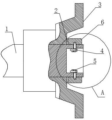
[0021] Example 1: Combining figure 1 As shown, a rear axle main reducer wheel rim structure, the end of the output shaft 1 is installed with a slewing support structure and a connecting flange 3 . The slewing support structure is connected with the vehicle frame to ensure the rotary output of the output shaft 1 .

[0022] The improvements of this embodiment are:

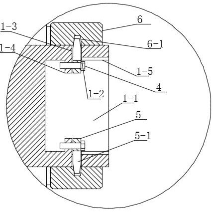
[0023] The end of the output shaft 1 is provided with an external thread, and the fastening nut 6 is threadedly installed on the end of the output shaft 1 to compress the connecting flange 3 on the output shaft 1 . A washer 2 is arranged between the fastening nut 6 and the connecting flange 3 . The inner wall of the fastening nut 6 is provided with an anti-retreat groove 6-1, the cross section is trapezoidal, and the two sides are inclined.

[0024] The shaft center of the end face of the output shaft 1 is provided with a central counterbore 1-1, and the inner wall of the central counterbore 1-1 is provided with a...

Embodiment 2

[0027] Embodiment 2: A method for processing the wheel edge structure of the rear axle final drive, on the basis of the above embodiment 1, combined with figure 2 shown;

[0028] Step 1: Set the connecting flange 3 on the end of the output shaft 1, install the washer 2 and the fastening nut 6, so that the washer 2 and the fastening nut 6 are tightly pressed on the outside of the connecting flange 3.

[0029] Step 2: install the elastic ring 5, place the end of the stop shaft 5-1 on the elastic ring 5 in the guide groove 1-5 and push it inward, and the stop shaft 5-1 slides into the inclined through hole 1-3; When the oblique through hole 1-3 on the output shaft 1 is longer and the anti-retraction shaft 5-1 of the elastic ring 5 is difficult to enter, the elastic ring 5 can be made into two independent parts and installed respectively.

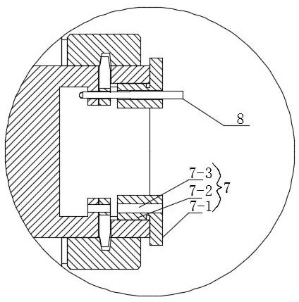
[0030] Step 3: On-site drilling on the elastic ring 5 and the block 1-4; the guide sleeve 7 is annular, the outer end surface of the guide s...


PUM


Abstract

The invention discloses a wheel edge structure and a processing method of a rear axle final reducer, belonging to the technical field of vehicle axle reducers. Including the output shaft, the slewing bearing structure and the connecting flange; the fastening nut presses the connecting flange on the output shaft; the inner wall of the fastening nut is provided with an anti-retreat groove; the inner wall of the counterbore in the center of the end face of the output shaft is provided with a positioning groove; Inclined through hole; the elastic ring with a fracture is installed in the positioning groove of the center counterbore, and the outer end of the anti-retreat shaft on the outer peripheral surface of the elastic ring passes through the inclined through hole and is placed in the anti-retreat groove; the stopper between the elastic ring and the central counterbore There are corresponding mounting holes and are fixedly connected by screws. The invention restricts the retreat of the fastening nut through the built-in elastic ring, prevents the nut from vibrating and loosening, and does not increase the axial dimension of the whole mechanism; the guide sleeve can ensure the installation accuracy of the screw and avoid the situation that the screw is difficult to install.

Description

technical field [0001] The invention relates to the technical field of vehicle axle reducers, in particular to a rear axle main reducer wheel edge structure and a processing method. Background technique [0002] The wheel reducer is the last stage reduction device in the automobile transmission system. Its function is to reduce the speed and torque transmitted by the main reducer and increase the torque, and then transmit it to the wheel hub, so that the wheel will produce a higher torque under the reaction of the ground adhesion. Large driving force, wheel reducers are widely used in trucks, large buses, off-road vehicles and some other large industrial and mining vehicles. The wheel side assembly of the existing vehicle axle reducer needs to be fastened and locked with the supporting shaft at the end of the vehicle axle to prevent the wheel side assembly from losing connection with the vehicle axle, thus endangering the driving safety. The wheel side locking structure of ...

Claims


Application Information

Patent Timeline
Patent Type & Authority Patents(China)
IPC IPC(8): B60B35/12B60K17/04
CPCB60B35/122B60K17/043
Inventor 任小红王亚飞
Owner 徐州万泽机械科技有限公司
Why Eureka
Try Eureka