
Anti-vibration outer circle shaft end turning machining device

A processing device and anti-vibration technology, applied in turning equipment, turning equipment, metal processing equipment, etc., can solve problems affecting construction accuracy, complex turning methods, difficult disassembly of turning heads, etc., to improve construction efficiency, quality and efficiency, The effect of meeting the turning construction requirements and improving the turning precision

Pending Publication Date: 2019-03-08
罗甸县金泰模具机械制造有限公司
View PDF0 Cites 0 Cited by
  • Summary
  • Abstract
  • Description
  • Claims
  • Application Information

AI Technical Summary

Problems solved by technology

Due to the large size and complex structure of the existing cylindrical grinder, the turning head is difficult to disassemble and assemble. During the processing and production process, the turning head is often shut down for maintenance due to the damage of the turning head
Moreover, after the base and the column of the cylindrical grinder are assembled and connected, the bolts connecting the base and the column are likely to loosen due to the vibration of the turning head during the turning process during use, making the assembly of the column and the base unstable, thereby affecting the construction accuracy
[0003] Therefore, in the existing cylindrical grinding machine, the connection method of the turning head is relatively complicated, and the turning method is relatively complicated, and the turning head is difficult to disassemble and replace; there is also a connection screw between the base and the column that is easily loosened by vibration, resulting in unstable assembly of the column and the base , the problem of low turning construction accuracy

Method used


Image

  • Anti-vibration outer circle shaft end turning machining device
  • Anti-vibration outer circle shaft end turning machining device
  • Anti-vibration outer circle shaft end turning machining device

Examples


Embodiment Construction

[0029] The present invention will be further described below in conjunction with the accompanying drawings and embodiments, but not as a basis for limiting the present invention.

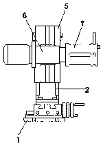
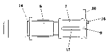
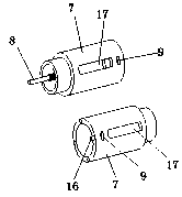
[0030] Example. Anti-vibration cylindrical spindle head turning device, such as Figure 1 to Figure 10 As shown, a base 1 is included, and a column 2 is arranged above the base 1, and the base 1 and the column 2 are connected through an anti-vibration device. The frame plate 4, the fixed seat 3 is connected with the fixed frame plate 4; a slider 5 is provided on one side of the column 2, and a shaft head turning device is provided on the slider 5, and the shaft head turning device includes a connecting installation shaft 6, which is connected to One end of the installation shaft 6 is provided with a motor, and the other end of the connection installation shaft 6 is provided with an outer circle turning head, and the outer circle turning head includes a turning case 7, and the closed end of the turn...


PUM


Abstract

The invention discloses an anti-vibration outer circle shaft end turning machining device. The device comprises a base, wherein stand columns are arranged above the base, and the base is connected with the stand columns through an anti-vibration device; the anti-vibration device comprises a fixing base connected with the base and the fixing frame plate arranged at the bottoms of the stand columns,and the fixing base is connected with the fixing frame plate; and a sliding block is arranged on one sides of the stand columns, and a shaft end turning device is arranged on the sliding block. The device is small in size, convenient to carry, convenient to use, easy to detach and convenient to maintain and replace; the construction requirements of the outer circle shaft end turning are met, andthe construction quality and efficiency are improved; and meanwhile, the vibration generated by the stand columns in the construction process can be effectively prevented, the connection screws between the base and the stand columns are prevented from being loosened through the vibration, so that the connection between the base and the stand columns is more stable, and then the turning machining precision is improved.

Description

technical field [0001] The invention relates to an outer cylindrical grinder, in particular to an anti-vibration outer cylindrical shaft head turning processing device. Background technique [0002] Cylindrical grinding machine is a grinding machine for processing the outer surface and shoulder end surface of the workpiece cylindrical, conical or other shapes; it is the most widely used and can process various cylindrical conical outer surfaces and shoulder end surface grinding machines. Due to the large size and complex structure of the existing cylindrical grinding machine, the turning head is difficult to disassemble and assemble. During the processing and production process, the machine is often shut down for maintenance due to the damage of the turning head. Moreover, after the base and the column of the cylindrical grinding machine are assembled and connected, the bolts connecting the base and the column are likely to loosen due to the vibration of the turning head dur...

Claims


Application Information

Patent Timeline
Patent Type & Authority Applications(China)
IPC IPC(8): B23B5/08B23Q11/00
CPCB23B5/08B23Q11/0032
Inventor 刘海
Owner 罗甸县金泰模具机械制造有限公司
Learn More