Fuel gas mixer structure

A gas mixer, gas technology, applied in combustion engines, machines/engines, internal combustion piston engines, etc., can solve problems such as poor gas mixing effect, and achieve improved mixing efficiency, mixing efficiency and effect, and stable concentration control. Effect

Pending Publication Date: 2021-10-01
ZHEJIANG RUIXING CARBURETOR MFG
View PDF0 Cites 0 Cited by
  • Summary
  • Abstract
  • Description
  • Claims
  • Application Information

AI Technical Summary

Problems solved by technology

[0004] The purpose of the present invention is to provide a gas mixer structure to solve the problem that the gas and air in the existing gas mixer rely on the simple diffusion of gas inside to achieve mixing, which leads to poor gas mixing effect

Method used


Image

  • Fuel gas mixer structure
  • Fuel gas mixer structure
  • Fuel gas mixer structure

Examples


Embodiment Construction

[0021] The specific implementation manners of the present invention will be further described in detail below in conjunction with the accompanying drawings and embodiments. The following examples are used to illustrate the present invention, but are not intended to limit the scope of the present invention.

[0022] In the description of the present invention, it should be understood that the orientations or positional relationships indicated by the terms "upper", "lower", "left", "right", "top", "bottom" etc. are based on those shown in the drawings. Orientation or positional relationship is only for the convenience of describing the present invention and simplifying the description, and does not indicate or imply that the referred device or element must have a specific orientation, be constructed and operated in a specific orientation, and thus should not be construed as a limitation of the present invention.

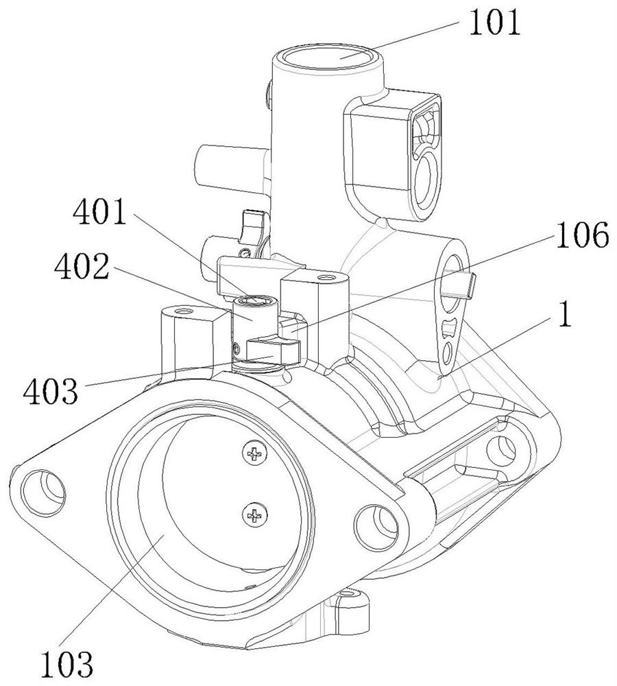
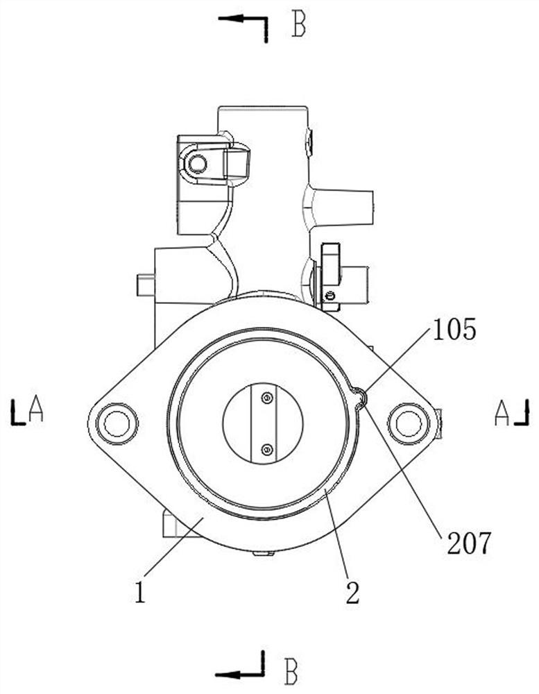
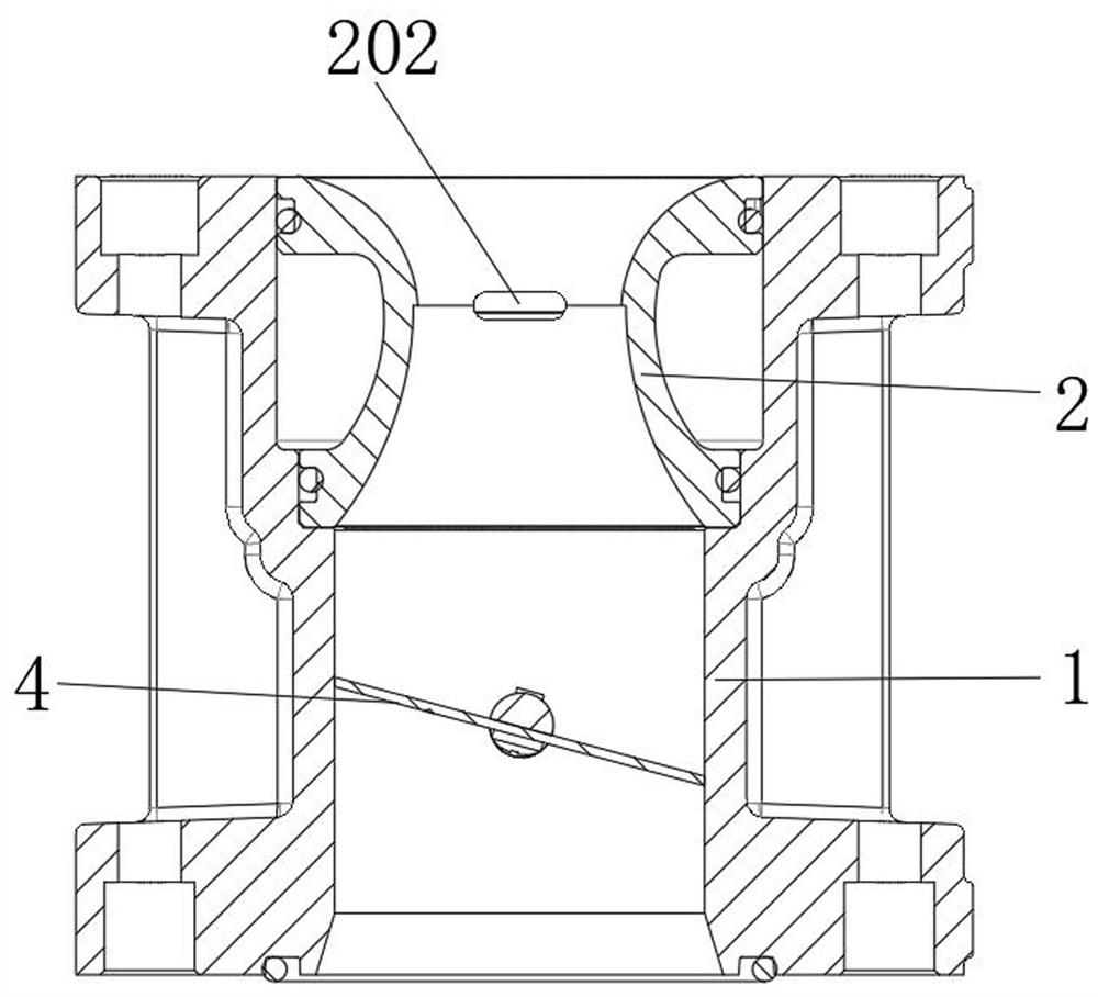
[0023] combine Figure 1~6 As shown, a gas mixer structure of an...


PUM


Abstract

The invention discloses a fuel gas mixer structure. According to the fuel gas mixer structure, air enters a main channel through an air inlet, fuel gas enters from a fuel gas inlet, and then enters an arc-shaped pipe through a gas inlet groove of the arc-shaped pipe be mixed with the air entering the arc-shaped pipe, due to the fact that the gas inlet groove is a square groove, the fuel gas can enter the arc-shaped pipe in a sheet shape along the square gas inlet groove, and in addition, due to the fact that the arc-shaped pipe is in an arc shape, the gas inlet groove is provided with a first step portion, and the inner wall of the arc-shaped pipe is provided with a second step portion opposite to the first step portion, and when air enters the arc-shaped pipe from the air inlet, the sudden cross section change enables the air to form swirling flow at the first step portion and the second step portion. The gas discharged from the gas inlet groove can be more uniformly mixed with air under the swirling flow effect, the mixing efficiency and effect are obviously improved, the concentration control of combustible gas is more stable, and the acceleration performance of an engine is further ensured.

Description

technical field [0001] The invention relates to the technical field of engines, in particular to a gas mixer structure. Background technique [0002] The engine that uses gas as fuel has a specific gas supply pipeline, which basically includes a pipeline for delivering gas, a pipeline for delivering air and a mixer, the pipeline for delivering gas is connected to the pipeline for delivering air and the mixer, and the mixer is connected to the engine The connection forms the mixture into the engine. [0003] The existing mixer is equipped with an air inlet and a gas inlet, and the gas and air are mixed at the valve plate of the mixer. This kind of mixing is realized by the diffusion of air and gas inside the mixer, and the mixing effect of the gas is not good. Well, especially during the acceleration process, the concentration control of combustible gas is unstable, which directly leads to poor acceleration performance of the engine, and in severe cases, directly leads to se...

Claims


Application Information

Patent Timeline
Patent Type & Authority Applications(China)
IPC IPC(8): F02M21/04
CPCF02M21/04Y02T10/30
Inventor 陈其安王学盛
Owner ZHEJIANG RUIXING CARBURETOR MFG
Why Eureka
Try Eureka