Fan lamp

A technology of fan lights and fan components, applied in lighting and heating equipment, liquid fuel engines, mechanical equipment, etc., can solve the problems of poor wind effect and small fan blade expansion angle, achieve good wind effect and avoid interference Effect

Pending Publication Date: 2021-10-01
OPPLE LIGHTING ELECTRICAL ZHONG SHAN CO LTD +1
View PDF0 Cites 0 Cited by
  • Summary
  • Abstract
  • Description
  • Claims
  • Application Information

AI Technical Summary

Problems solved by technology

[0004] The purpose of the present invention is to solve the problems of the existing fan lights with small fan blade expansion angle and poor wind effect, and to provide a fan light with a new synchronous structure

Method used


Image

  • Fan lamp
  • Fan lamp
  • Fan lamp

Examples


Embodiment Construction

[0026] The fan proposed by the present invention will be further described in detail below in conjunction with the accompanying drawings and specific embodiments.

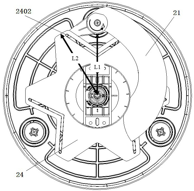
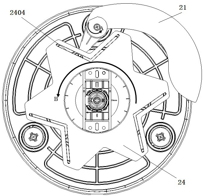
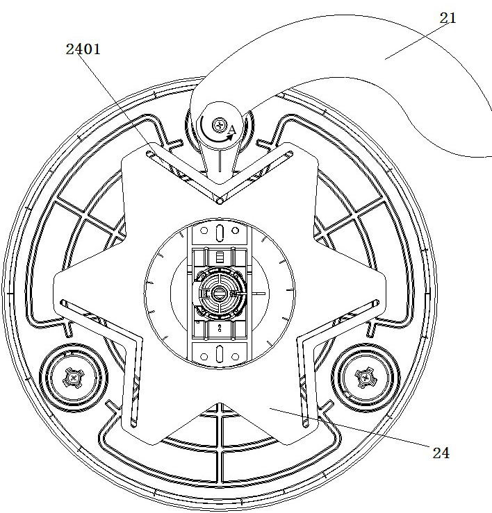
[0027] figure 2 It shows a preferred implementation of the fan lamp of the present application, and its explosion diagram is as follows figure 1 As shown, the fan lamp includes a mounting base 4 , a suspension rod 3 , a fan assembly 2 and a lamp assembly 1 . The mounting base 4 is fixedly installed on the roof and the installation foundation of the beam lamp. One end of the suspender 3 is connected to the mounting base 4 , and the other end is connected to the lamp assembly 1 and the fan assembly 2 . In this embodiment, the suspension rod 3 is screwed to the fixed axis of the motor 23 in the fan assembly 2, and the lamp assembly 1 is connected to the lower end of the fixed axis, which is equal to the extension of the suspension rod 3. In other preferred embodiments, the lamp assembly 1 and the fan assembly 2 can...


PUM


Abstract

The invention provides a fan lamp. The fan lamp is characterized in that the fan blades are connected through a synchronizing mechanism, and sliding grooves in synchronizing rings are in a V shape; due to the shape of the sliding grooves, when the fan blades are opened, the selecting directions of the synchronizing rings in the two V-shaped sliding grooves with different angles are different, so that interference to the roots of the fan blades can be avoided, large-angle rotation of the fan blades is achieved, and therefore, a better air outlet effect is generated.

Description

technical field [0001] The invention relates to the technical field of fan lamps, in particular to a fan lamp with an improved structure. Background technique [0002] The fan blades of the invisible fan light can be retracted. When not in use, the fan blades are hidden above the lamp, and the fan blades are unfolded when in use. The invisible fan has multiple blades. In order to ensure the normal use of the product, the blades need to be synchronized when they are unfolded and closed. Therefore, the related products on the market basically have a synchronous structure. In the existing design, multiple fan blades are connected to each other through a synchronous ring, so that each fan blade rotates synchronously. The synchronous ring is usually a circular ring. When setting the synchronous ring, in order to prevent the synchronous ring from affecting the rotation of the fan blades, the size of the synchronous ring is limited. This restriction affects the expansion range of ...

Claims


Application Information

Patent Timeline
Patent Type & Authority Applications(China)
IPC IPC(8): F04D25/08F04D29/00F04D29/36F21V33/00
CPCF04D25/088F04D29/002F04D29/005F04D29/362F21V33/0096
Inventor 王小磊周定德张国宝李尚李华琦
Owner OPPLE LIGHTING ELECTRICAL ZHONG SHAN CO LTD
Why Eureka
Try Eureka