Eureka AIR delivers breakthrough ideas for toughest innovation challenges, trusted by R&D personnel around the world.

Submersible full-through-flow gate pump with front guiding vane with adjustable placing angle

An adjustable technology with front guide vanes, which is applied in the direction of cross-flow pumps, circulation pumps, pumping devices for elastic fluids, etc., and can solve the problem of difficult to achieve accurate flow adjustment and single working conditions of full-through-flow gate pumps, etc. problems, to achieve the effect of reducing water evaporation loss, reducing water pollution from multiple sources, and achieving significant social and economic benefits

Pending Publication Date: 2021-10-01
CHANGJIANG SURVEY PLANNING DESIGN & RES
View PDF4 Cites 0 Cited by
  • Summary
  • Abstract
  • Description
  • Claims
  • Application Information

AI Technical Summary

Problems solved by technology

[0006] The purpose of the present invention is to overcome the shortcomings of the above-mentioned background technology, and provide a submersible full-through flow gate pump with an adjustable front guide vane to solve the problem that the existing full-through-flow gate pumps have relatively single working conditions, It is difficult to realize the defect of accurate flow adjustment, and then realize the precise and intelligent adjustment of water supply flow

Method used


Image

  • Submersible full-through-flow gate pump with front guiding vane with adjustable placing angle
  • Submersible full-through-flow gate pump with front guiding vane with adjustable placing angle
  • Submersible full-through-flow gate pump with front guiding vane with adjustable placing angle

Examples


Embodiment Construction

[0028] The implementation of the present invention will be described in detail below in conjunction with the accompanying drawings, but they do not constitute a limitation to the present invention, and are only examples. At the same time, the advantages of the present invention will become clearer and easier to understand through the description.

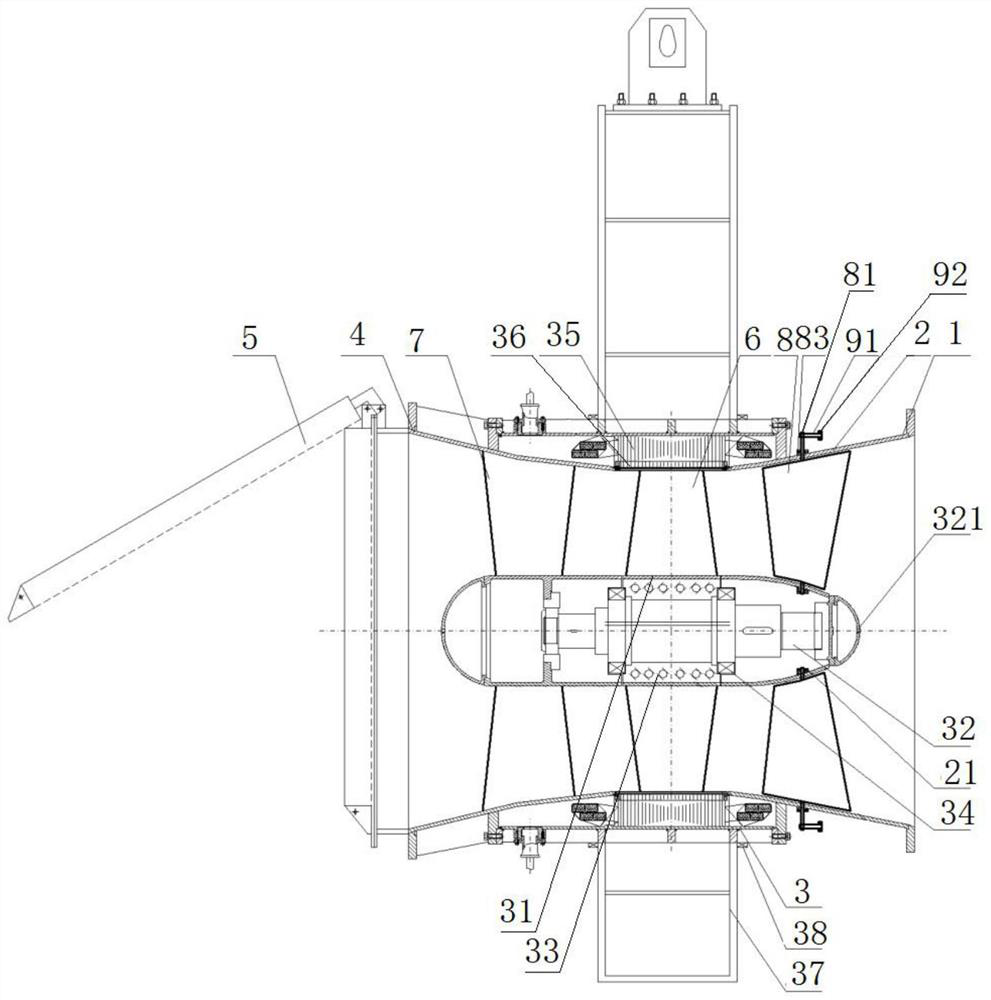
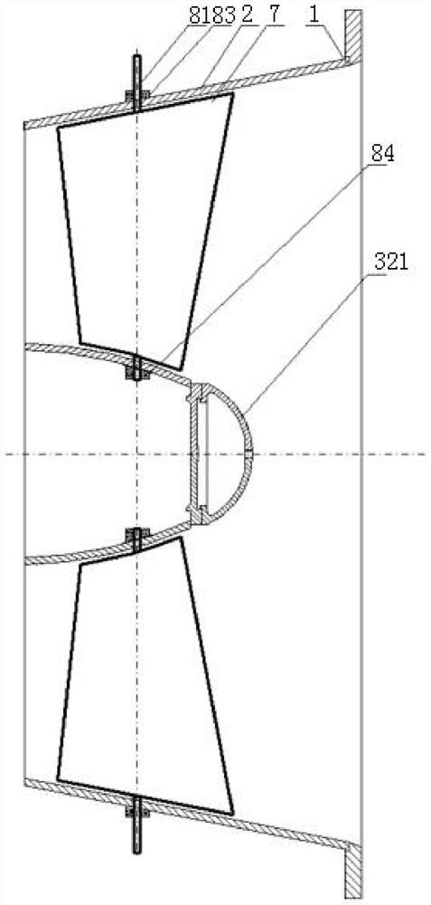
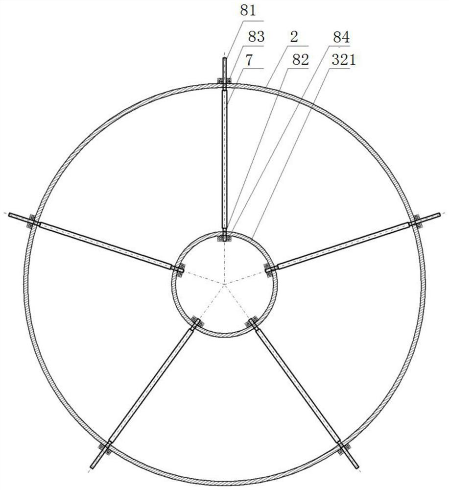
[0029] Referring to the accompanying drawings, we can see that: figure 1 As shown, the submersible full-through flow gate pump with adjustable front guide vanes, from the water inlet to the outlet, includes water inlet bell mouth 1, front guide vane body 2, pump casing 3, and rear guide vane body 4 And flap door 5; There is an impeller hub 31 in the front guide vane body 2, the pump casing 3 and the rear guide vane body 4; a stator 36 is arranged in the pump casing 3, and a rotor 35 is arranged in the stator 36;

[0030] One end of the impeller 6 is welded to the inner cavity of the rotor 35, and the other end is connected to the i...


PUM


Abstract

The invention discloses a submersible full-through-flow gate pump with a front guiding vane with an adjustable placing angle, and relates to the field of water conservancy and water affairs and fluid machinery optimization design. The submersible full-through-flow gate pump with the front guiding vane with the adjustable placing angle sequentially comprises a water inlet horn mouth, a front guiding vane body, a pump shell, a rear guiding vane body and a flap valve from a water flow inlet to a water flow outlet, wherein impeller hubs are arranged in the front guiding vane body, the pump shell and the rear guiding vane body; stators are arranged in the pump shell, and rotors are arranged in the stators; one ends of impellers are welded with inner cavities of the rotors, and the other ends are connected with the impeller hubs; pump shafts are arranged in the impeller hubs, and the inner parts of the impeller hubs are connected with the pump shafts through pump shaft bearings; one end of a rear guiding vane is welded with an inner cavity of the rear guiding vane body, and the other end is connected with the impeller hubs. According to the submersible full-through-flow gate pump with the front guiding vane with the adjustable placing angle, by adjusting the placing angle of the front guiding vane, accurate and intelligent adjustment of the water supply flow of a main canal can be achieved, and then the traditional working mode that the overflowing flow is adjusted by changing the lifting amplitude of a gate along a line is replaced.

Description

technical field [0001] The invention relates to the fields of water conservancy and water affairs and fluid machinery optimization design, more specifically, it is a submersible full-through flow gate pump with adjustable front guide vanes. Background technique [0002] Long-distance main water conveyance canals, especially artificial water conveyance main canals, generally adopt the artesian water supply method. For example, the 1200-km-long main water conveyance main canal of the South-to-North Water Diversion Project uses artesian water supply throughout, and a total of controlling functions are set up on the main canals. There are 64 gates. [0003] Long-distance main water conveyance canals have different water flow requirements in different time periods; under traditional working methods, the overcurrent flow is generally adjusted by changing the lifting range of gates along the line. This method has insufficient joint scheduling accuracy, and if the gates are long It...

Claims


Application Information

Patent Timeline
Patent Type & Authority Applications(China)
IPC IPC(8): F04D29/40F04D29/00F04D15/00F04D13/08F04D5/00
CPCF04D29/406F04D29/007F04D15/00F04D13/086F04D5/00
Inventor 章勋桂绍波梁波王华军陈笙彭志远郑涛平
Owner CHANGJIANG SURVEY PLANNING DESIGN & RES
Why Eureka
Eureka Blog
Learn More