
Snap ring pressing plate unit connected through three-point protruding snap ring

A technology of pressing plate and snap ring, which is applied in the direction of bearing components, anti-centrifugal force rotating parts, rigid supports of bearing parts, etc., which can solve the problems of loose bearing outer ring, interference friction, and reducing the service life of snap ring pressing plates, etc.

Inactive Publication Date: 2021-10-01
C&U CO LTD +2
View PDF0 Cites 0 Cited by
  • Summary
  • Abstract
  • Description
  • Claims
  • Application Information

AI Technical Summary

Problems solved by technology

[0003] First of all, in the process of connecting and matching the existing snap ring pressure plate and the bearing outer ring, the looseness of the bearing outer ring often occurs, and the existing snap ring pressure plate lacks a fastening adjustment mechanism to adjust the loose bearing outer ring. The problem of adjusting the tightness, followed by the existing snap ring pressure plate in the process of cooperating with the bearing often causes the interference of parts to increase the friction force, thereby reducing the service life of the snap ring pressure plate

Method used


Image

  • Snap ring pressing plate unit connected through three-point protruding snap ring
  • Snap ring pressing plate unit connected through three-point protruding snap ring
  • Snap ring pressing plate unit connected through three-point protruding snap ring

Examples


Embodiment Construction

[0026] The following will clearly and completely describe the technical solutions in the embodiments of the present invention with reference to the accompanying drawings in the embodiments of the present invention. Obviously, the described embodiments are only some, not all, embodiments of the present invention. Based on the embodiments of the present invention, all other embodiments obtained by persons of ordinary skill in the art without making creative efforts belong to the protection scope of the present invention.

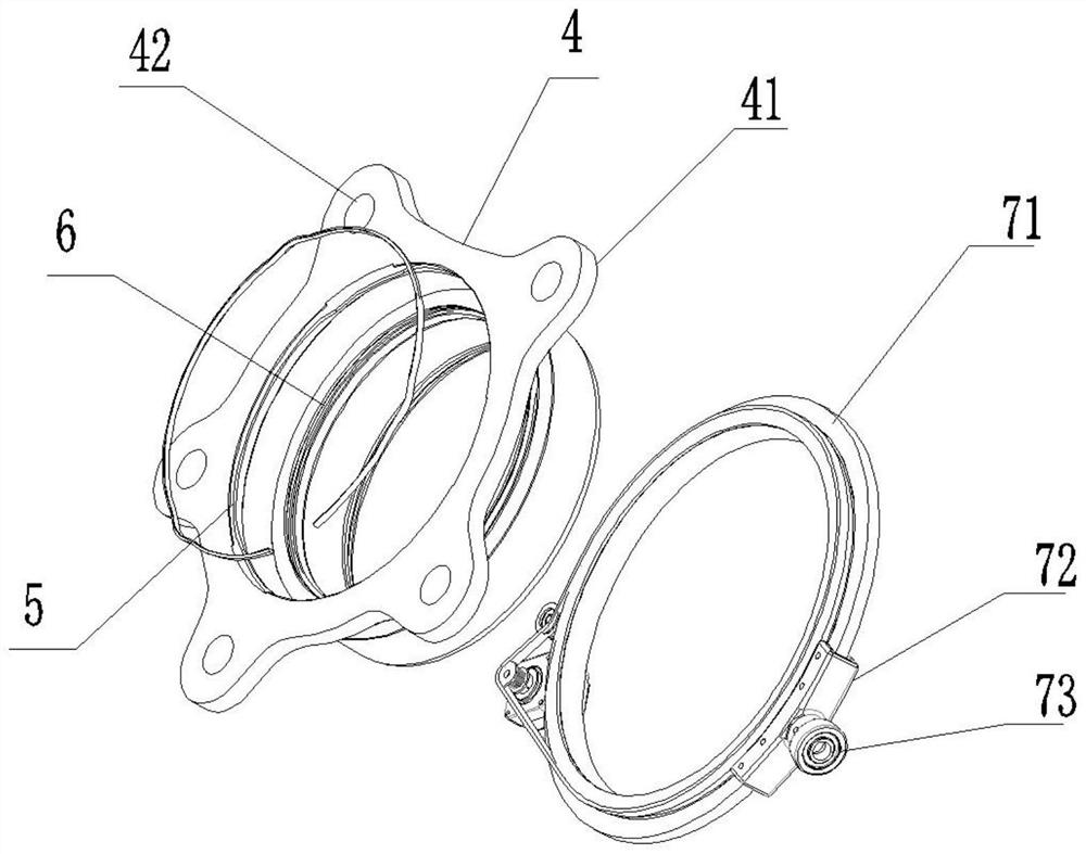
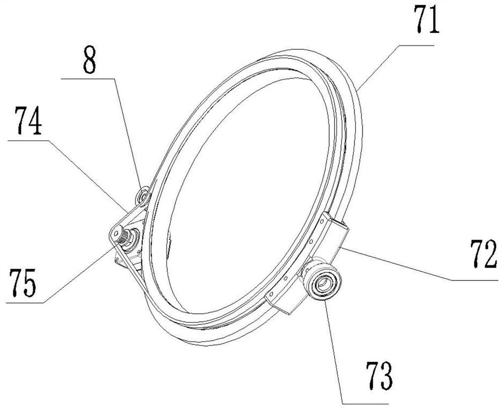
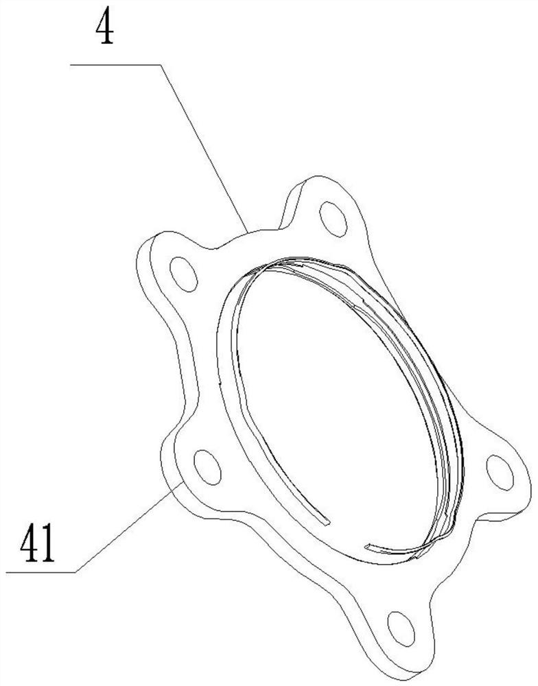
[0027] The present invention provides such Figure 1-7 A clasp platen unit connected by three-point protruding clasps is shown, and the clasp platen unit connected by three-point protruding clasps includes a clasp structure 1, which is clamped and fixed inside the platen structure 4 On the surface, the outer surface of the pressure plate structure 4 is provided with a pressure plate boss 41, and a circular pressure plate hole 42 is opened at the center line of...


PUM


Abstract

The invention relates to the field of snap ring pressing plate units, in particular to a snap ring pressing plate unit connected through a three-point protruding snap ring. The snap ring pressing plate unit comprises a snap ring structure, the snap ring structure is clamped on and fixed to the inner surface of a pressing plate structure, pressing plate bosses are arranged on the outer surface of the pressing plate structure, and a circular pressing plate hole is formed in the center line of each pressing plate boss. A pressing plate bearing fastening adjusting ring structure is arranged on the outer surface of the lower end of the pressing plate structure, and the clamping ring structure, the pressing plate structure and the pressing plate bearing fastening adjusting ring structure form the clamping ring pressing plate unit. By means of the clamping ring pressing plate unit composed of the clamping ring structure, the pressing plate structure and the pressing plate bearing fastening adjusting ring structure, the tightness of a loose bearing outer ring can be effectively adjusted, and a bearing is effectively prevented from falling off; and by means of clamping ring protrusions arranged on the outer surface of an annular clamping ring, parts of the bearing outer ring are effectively blocked, interference between the parts is effectively prevented, and friction is effectively reduced.

Description

technical field [0001] The invention relates to the field of a snap ring pressing plate unit, in particular to a snap ring pressing plate unit connected by three-point raised snap rings. Background technique [0002] The snap ring press unit is mainly used in conjunction with the connection of the outer ring of the bearing, but the existing snap ring press unit has some shortcomings in the process of use and needs to be improved. Some shortcomings are as follows: [0003] First of all, in the process of connecting and matching the existing snap ring pressure plate and the bearing outer ring, the looseness of the bearing outer ring often occurs, and the existing snap ring pressure plate lacks a fastening adjustment mechanism to adjust the loose bearing outer ring. The problem of adjusting the tightness, followed by the existing snap ring pressure plate in the process of cooperating with the bearing, often causes the interference of parts to increase the friction force, thereb...

Claims


Application Information

Patent Timeline
IPC IPC(8): F16C35/06F16C35/077
CPCF16C35/06F16C35/077F16C2229/00F16C2226/70
Inventor 徐家良白雪峰张树武
Owner C&U CO LTD
Learn More