Oil separator, oil return system and refrigerating system

A technology of oil separator and oil return system, which is applied in refrigerators, refrigeration components, refrigeration and liquefaction, etc., and can solve the problem that the oil separator cannot return oil in time and the speed of oil return

Active Publication Date: 2021-10-01
QINGDAO HAIER AIR CONDITIONING ELECTRONICS CO LTD +2
View PDF12 Cites 0 Cited by
  • Summary
  • Abstract
  • Description
  • Claims
  • Application Information

AI Technical Summary

Problems solved by technology

[0005] In order to solve the above-mentioned problems in the prior art, that is, in order to solve the technical problems that the oil separator in the prior art cannot return oil in time and the oil return speed is slow, the present invention provides an oil separator

Method used


Image

  • Oil separator, oil return system and refrigerating system
  • Oil separator, oil return system and refrigerating system
  • Oil separator, oil return system and refrigerating system

Examples


Embodiment Construction

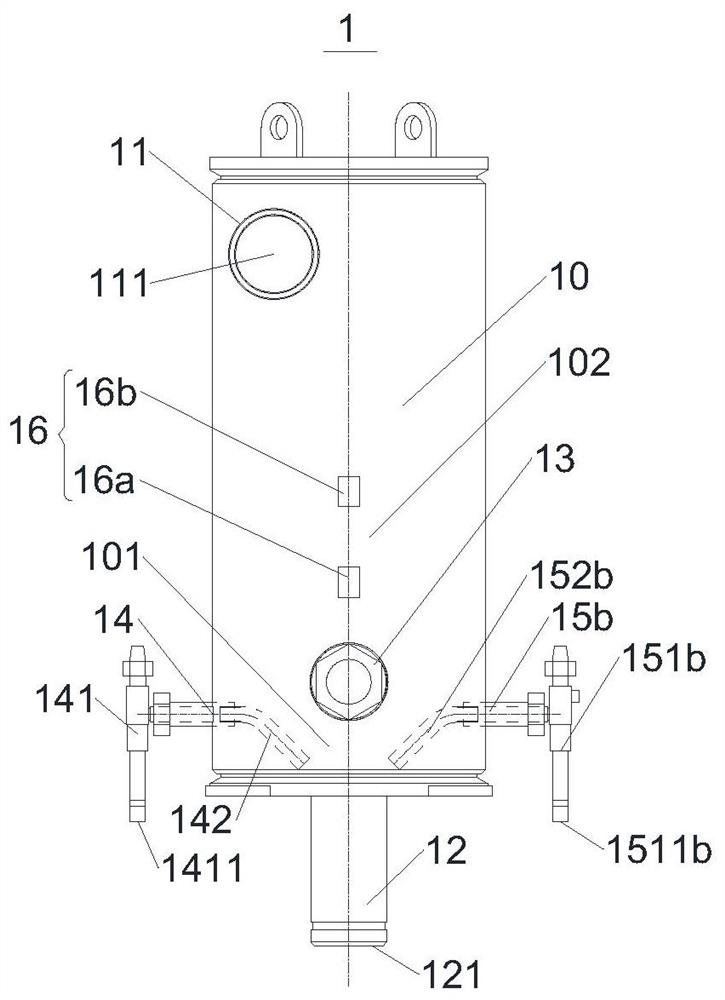
[0023] Preferred embodiments of the present invention are described below with reference to the accompanying drawings. Those skilled in the art should understand that these embodiments are only used to explain the technical principles of the present invention, and are not intended to limit the protection scope of the present invention.

[0024] It should be noted that, in the description of the present invention, terms such as "upper", "lower", "left", "right", "inner", "outer" and other indicated directions or positional relationships are based on the terms shown in the accompanying drawings. The direction or positional relationship shown is only for convenience of description, and does not indicate or imply that the device or element must have a specific orientation, be constructed and operated in a specific orientation, and thus should not be construed as limiting the present invention. In addition, the terms "first" and "second" are used for descriptive purposes only, and ...


PUM


Abstract

The invention relates to an oil separator, an oil return system and a refrigerating system. The oil separator comprises a cylinder, a basic oil return opening formed in the lower part of the cylinder, at least one enhanced oil return opening, and at least one oil level switch; each enhanced oil return opening and the basic oil return opening are spaced from each other on the cylinder; and each oil level switch is arranged on the side wall of the cylinder, each oil level switch corresponds to one enhanced oil return opening, and the corresponding oil level height in the cylinder is monitored, and each enhanced oil return opening is lower than any one of the at least one oil level switch in the height direction of the cylinder. According to the oil separator, oil can be returned in time, and the oil return efficiency is remarkably improved. The invention further discloses the oil return system and the refrigerating system comprising the oil separator.

Description

technical field [0001] The invention relates to a refrigeration system, in particular to an oil separator, an oil return system and a refrigeration system. Background technique [0002] A refrigeration system usually includes four basic components, a compressor, a condenser, a throttling mechanism, and an evaporator, which can form a circuit that allows the refrigerant to circulate in it, and the compressor is used to compress the low-temperature and low-pressure gas refrigerant into a high-temperature and high-pressure one. gas refrigerant. Compressors, such as scroll compressors, centrifugal compressors, screw compressors, etc., often require lubricating oil to lubricate and seal their moving parts during work. Therefore, when the compressed high-temperature and high-pressure gas refrigerant in the compressor is discharged from the compressor very quickly, the lubricating oil in the compressor easily forms oil vapor and oil droplet particles and is discharged together wit...

Claims


Application Information

Patent Timeline
Patent Type & Authority Applications(China)
IPC IPC(8): F25B31/00F25B41/20F25B43/02F25B49/02
CPCF25B31/004F25B41/20F25B43/02F25B49/02Y02B30/70
Inventor 张志平杨云龙张瑞台安普光张捷
Owner QINGDAO HAIER AIR CONDITIONING ELECTRONICS CO LTD
Why Eureka
Try Eureka