Assembling device and method for ball cage coupling hoop

A technology for assembly devices and couplings, applied in metal processing, metal processing equipment, manufacturing tools, etc., can solve problems such as low work efficiency and high labor intensity, and achieve high labor intensity, low work efficiency, and compact structure Effect

Active Publication Date: 2021-10-08
湖北唯思凌科装备制造有限公司
View PDF4 Cites 0 Cited by
  • Summary
  • Abstract
  • Description
  • Claims
  • Application Information

AI Technical Summary

Problems solved by technology

[0006] The object of the present invention is to provide a compact structure and ingenious design to solve the problems of high labor intensity and low work efficiency in the manual assembly of cage coupling hoops. The assembly device of the ball cage coupling clamp of the problem

Method used


Image

  • Assembling device and method for ball cage coupling hoop
  • Assembling device and method for ball cage coupling hoop
  • Assembling device and method for ball cage coupling hoop

Examples


Embodiment Construction

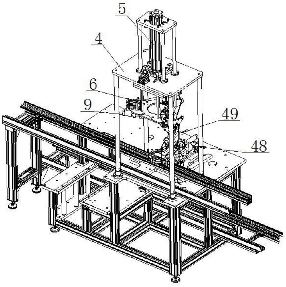
[0041] The assembly device of the ball cage coupling clamp includes a frame 4, a positioner 48, a compactor 49, a pneumatic clamp 9, a lifting cylinder 5 and an assembly plate 6 (see the appendix image 3 with 4 ).

[0042] The top of the frame 4 is equipped with an assembly plate 6 through a lifting cylinder 5 (see the attached image 3 with 4 ); the center of the assembly plate 6 is provided with an avoidance hole 47 (see the attached manual Figure 13 ). The lifting cylinder 5 can drive the mounting plate 6 to move up and down during work.

[0043] The bottom end of the assembly plate 6 is evenly installed with three sets of slide seats 7 through the push cylinder 8 and the guide rail; the three sets of slide seats 7 are radially arranged, and the push cylinder 8 can drive the corresponding slide seat 7 to move back and forth toward the center of the assembly plate 6 when the push cylinder 8 is working .

[0044] Pneumatic clamp 9 is housed on the sliding seat 7 (refe...


PUM


Abstract

The invention relates to an assembling device for a ball cage coupling hoop, and belongs to the technical field of ball cage coupling assembling equipment. The assembling device for the ball cage coupling hoop comprises a rack, a positioner, a pressing device, pneumatic clamps, a lifting cylinder and an assembling plate, wherein the assembling plate is mounted at the top end of the rack through the lifting cylinder; three sliding seats are uniformly mounted at the bottom end of the assembling plate through pushing cylinders and guide rails; the pneumatic clamps are mounted on the sliding seats; the positioner is mounted at the portion, below the pneumatic clamps, on the rack; and the pressing device is mounted on one side of the positioner. The assembling device for the ball cage coupling hoop is compact in structure, ingenious in design and capable of mechanically completing the assembling work of the ball cage coupling hoop, so that the problems of high labor intensity and low working efficiency during manual assembling are solved, and the requirements of enterprises for efficient production, assembly and use are met.

Description

technical field [0001] The invention relates to an assembly device for a ball cage coupling hoop, belonging to the technical field of ball cage coupling assembly equipment. Background technique [0002] As a commonly used coupling, the ball cage coupling is especially suitable for shaft transmission under the conditions of large inclination angle and limited radial size. The surface of the ball cage coupling is equipped with a clamp 1 (see the attached figure 1 ); ball cage coupling clamp 1 (refer to the attached figure 2 ) are evenly arranged on the circumferential surface of three sets of "n"-shaped tightening protrusions 2; one end of the ball cage coupling clamp 1 is provided with a positioning piece 3; one end of the positioning piece 3 passes through the cage coupling clamp The other end of 1 extends to its outer side; at present, the clamp 1 of the ball cage coupling is mainly installed on the ball cage coupling manually by pressing and tightening the protrusion 2 ...

Claims


Application Information

Patent Timeline
Patent Type & Authority Applications(China)
IPC IPC(8): B23P19/00B23P19/027
CPCB23P19/001B23P19/027
Inventor 薛锋
Owner 湖北唯思凌科装备制造有限公司
Why Eureka
Try Eureka