Jacking bidirectional width adjusting mechanism

A technology of width adjustment and jacking, applied in the direction of conveyors, conveyor objects, transportation and packaging, etc., can solve problems such as cumbersome operation, increased equipment cost, and inability to meet modern concepts, and achieve high transmission efficiency and low friction loss Effect

Pending Publication Date: 2021-10-08
欧拓飞科技(珠海)有限公司
View PDF0 Cites 0 Cited by
  • Summary
  • Abstract
  • Description
  • Claims
  • Application Information

AI Technical Summary

Problems solved by technology

[0002] With the advancement of science and technology, industrial automation has been widely used. Most of the products with complex structures are assembled through the assembly line. For the parts that need to be transported with different specifications, it is obviously impossible to set up multiple conveyor tracks that are suitable for the parts. It conforms to the concept of modernization, and at the same time increases the cost of equipment. If the conveying track is set to a large track, it will be overkill for large parts, which will also increase the cost of equipment. If the transport track is set to a small track, it will not be possible to accurately locate large parts. However Most of the track lines in today's automated production are bound together with the belt line, the belt line on one side is fixed, and the track line on the other side moves to adapt to the size of various products, and it is impossible to directly move the product from the fixed module It can only be transferred directly to the track line by adding an additional mechanism. The buffer of the belt line is also realized by dividing the belt line into three sections. Such a track line is not only complex in structure, high in equipment cost, but also cumbersome in operation, which is not conducive to improving work efficiency, so it is necessary to provide a jacking two-way width adjustment mechanism that is simple in structure, easy to operate and capable of blocking positioning

Method used


Image

  • Jacking bidirectional width adjusting mechanism
  • Jacking bidirectional width adjusting mechanism
  • Jacking bidirectional width adjusting mechanism

Examples


Embodiment Construction

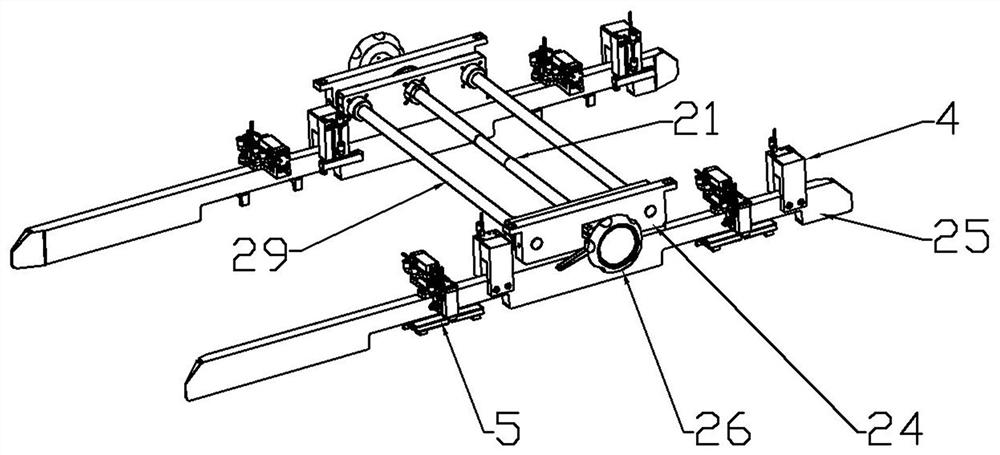
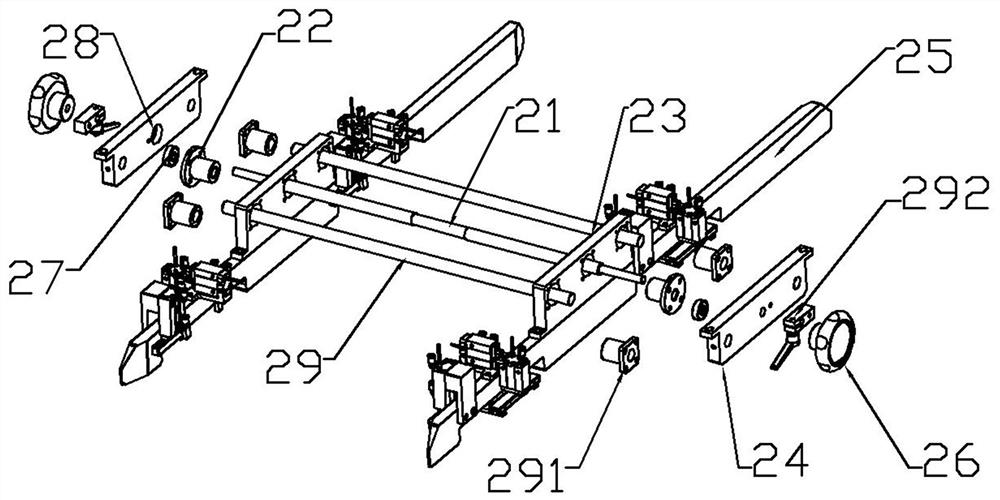
[0034] Such as Figure 1 to Figure 10As shown, in this embodiment, the present invention includes a track line module 1, a width adjustment module 2 and a jacking module 3, and the width adjustment module 2 includes a screw 21 and a width adjustment structure, and the width adjustment structure It includes a ball nut 22, a connection block 23, a first fixed block 24 and a rib 25, the ball nut 22 passes through the connection block 23 and is fixed on the outside of the connection block 23, and one end of the screw rod 21 passes through the Through the ball nut 22 and the first fixed block 24, the rib 25 is fixed on the connecting block 23 and parallel to the transport direction of the track line module 1, and the end of the screw rod 21 is set There is a handle 26, and the number of the width-adjusting structures is two groups, and the two groups of the width-adjusting structures are respectively arranged at the two ends of the screw rod 21 and located on both sides of the tran...


PUM


Abstract

The invention aims at providing a jacking bidirectional width adjusting mechanism. The jacking bidirectional width adjusting mechanism comprises a track line module, width adjusting modules, a jacking module, blocking modules and a positioning module. The width adjusting modules are arranged on the two sides of the conveying direction of the track line module, and the width adjusting modules can limit and fix materials on the track line module. The jacking module is arranged at the lower ends of the width adjusting modules, and the jacking module can lift the materials on the track line module to meet the requirement that the materials are transferred to stations with different heights. The blocking modules are used for blocking the materials on the track line module so that the next procedure can be carried out, and the blocking modules can also temporarily store the materials at the input end and the output end of the track line module. The positioning module can adjust and limit the materials on the track line module in the horizontal direction, the correct positions of the materials on the track line module are kept, the materials can be conveniently moved to the next station to be accurately positioned, and the jacking bidirectional width adjusting mechanism is applied to the technical field of material conveying tracks.

Description

technical field [0001] The invention is applied to the technical field of material transport rails, and in particular relates to a jacking two-way width adjustment mechanism. Background technique [0002] With the advancement of science and technology, industrial automation has been widely used. Most of the products with complex structures are assembled through the assembly line. For the parts that need to be transported with different specifications, it is obviously impossible to set up multiple conveyor tracks that are suitable for the parts. It conforms to the concept of modernization, and at the same time increases the cost of equipment. If the conveying track is set to a large track, it will be overkill for large parts, which will also increase the cost of equipment. If the transport track is set to a small track, it will not be possible to accurately locate large parts. However Most of the track lines in today's automated production are bound together with the belt lin...

Claims


Application Information

Patent Timeline
Patent Type & Authority Applications(China)
IPC IPC(8): B65G21/12B65G41/00B65G15/12B65G47/88B65G47/82B65G47/22
CPCB65G21/12B65G41/003B65G15/12B65G47/8807B65G47/82B65G47/22
Inventor 祁宏赛徐志兵张琛星
Owner 欧拓飞科技(珠海)有限公司
Why Eureka
Try Eureka