
Assembly type building cold bending profile

A prefabricated and architectural technology, applied in the direction of construction, building components, building structure, etc., can solve the problems of operator inconvenience, inconvenient movement, etc., and achieve the effect of simple assembly and fixation

Pending Publication Date: 2021-10-08
杨叶萍
View PDF11 Cites 0 Cited by
  • Summary
  • Abstract
  • Description
  • Claims
  • Application Information

AI Technical Summary

Problems solved by technology

[0005] The invention patent application with the application number CN202011200025.8 discloses a prefabricated profile component. This solution effectively reduces the The risk of shaking of the decorative strip improves the stability of the decorative strip, and achieves the effect of simple and reliable structure, common connection mode and easy installation and implementation; this scheme realizes simple and convenient assembly, but it is inconvenient to move it as a whole function, which brings inconvenience to the operator

Method used


Image

  • Assembly type building cold bending profile
  • Assembly type building cold bending profile
  • Assembly type building cold bending profile

Examples


no. 1 example

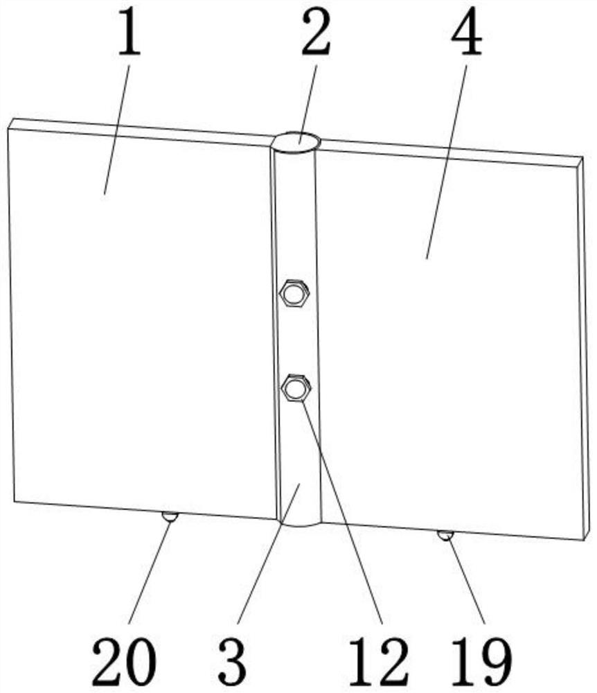
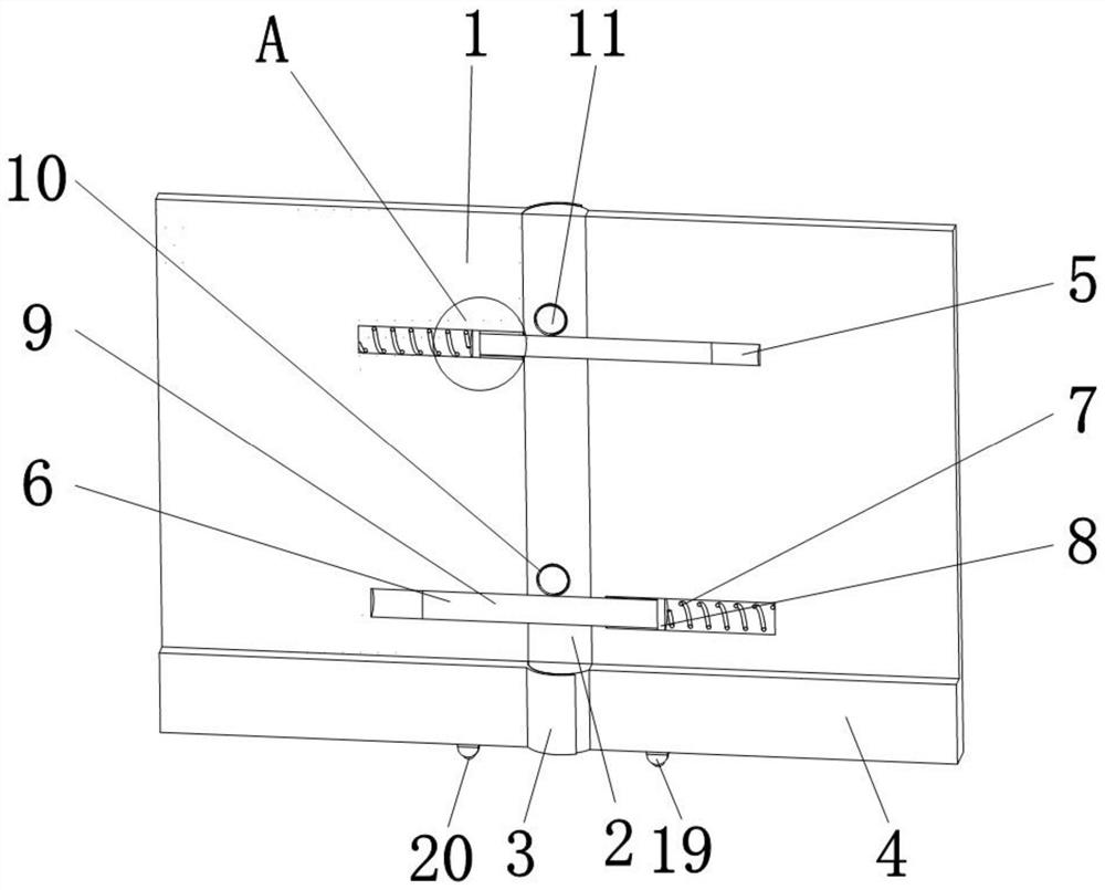
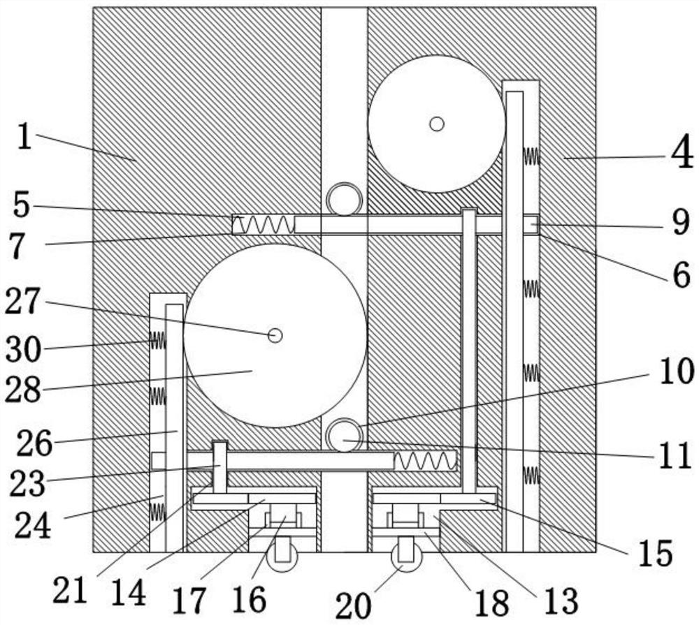
[0035] Such as Figure 1 to Figure 5 As shown, the present invention provides a prefabricated building cold-formed profile, including an assembly fixing plate 1, the right end of the assembly fixing plate 1 is provided with a fixed shaft 2, the outer surface of the fixed shaft 2 is movably socketed with a movable arc sleeve 3, and the movable arc The right end of the sleeve 3 is provided with an assembly movable plate 4, and one side of the assembly fixed plate 1 and the assembly movable plate 4 is provided with a mounting groove 5 and a fixing groove 6, the mounting groove 5 is opposite to the fixing groove 6, and the inner cavity of the mounting groove 5 The right side of the back spring 7 is provided with a return spring 7, the other end of the return spring 7 is provided with a connecting block 8, and the left side of the connecting block 8 is provided with a fixed rod 9, and the other end of the fixed rod 9 runs through the installation groove 5 and extends to the end of t...

no. 2 example

[0046] Based on a prefabricated building cold-formed profile provided in the first embodiment, the device uses rollers 20 to realize the movement and support of the device, but the rollers 20 alone are not enough to achieve stable support for the entire device, especially for disassembly. During installation, it is necessary to lift the assembly fixed plate 1 and the assembly movable plate 4. At this time, because the rotating gear rod 23 is located inside the notch 13, it is inconvenient to manually operate. After determining the appropriate assembly position, assemble the fixed plate 1 and The lowering height of the assembly movable plate 4 cannot be precisely and smoothly controlled, and when the assembly fixed plate 1 and the assembly movable plate 4 are assembled on uneven ground, the device can only provide temporary support through the rollers 20, and cannot guarantee the stability of the support sex. In order to solve this problem and ensure the stability, accuracy and...


PUM


Abstract

The invention belongs to the technical field of assembly profiles, and discloses an assembly type building cold bending profile. The assembly type building cold bending profile comprises an assembly fixing plate, wherein a fixing shaft is arranged at the right end of the assembly fixing plate, the outer surface of the fixing shaft is movably sleeved with a movable arc sleeve, an assembly movable plate is arranged at the right end of the movable arc sleeve, and mounting grooves are formed in the left side of the assembly movable plate. Through the arrangement of the mounting grooves, fixing rods and fixing grooves, due to the arrangement of the mounting grooves, mounting of reset springs, connecting blocks and the fixing rods can be facilitated, the effect of pushing the fixing rods into the fixing grooves can be achieved through the connecting blocks under the action of the reset springs, therefore an assembly fixing plate and an assembly movable plate are connected simply, and through cooperation of the movable arc sleeve, a bolt and a fixing sleeve, the effect that the assembly fixing plate and the assembly movable plate are fixed through a fixed shaft and the movable arc sleeve can be achieved, and therefore the purpose of simple assembly and fixation is achieved.

Description

technical field [0001] The invention belongs to the technical field of assembled profiles, in particular to an assembled building cold-formed profile. Background technique [0002] Prefabricated profiles are materials for building prefabricated buildings, while prefabricated buildings refer to the transfer of a large number of on-site operations in the traditional construction method to the factory, where the building components and accessories (such as floor slabs, wall panels, stairs, etc.) are processed and manufactured in the factory. , balcony, etc.), transported to the construction site, and assembled and installed on site through reliable connection methods. [0003] At present, with the rise of prefabricated buildings, more and more prefabricated profiles have emerged, and most of the existing prefabricated profiles can indeed achieve the function of building prefabricated buildings when used, but the existing assembly The type profile does not have a good space sto...

Claims


Application Information

Patent Timeline
Patent Type & Authority Applications(China)
IPC IPC(8): E04B1/344E04B2/74E04B2/82
CPCE04B1/3445E04B2/74E04B2/7405E04B2/827E04B1/34317
Inventor 杨叶萍
Owner 杨叶萍
Learn More