
Environment-friendly oil filter

An oil filter, an environmentally friendly technology, applied in the field of filters, can solve the problems of unusable resources, secondary wear of the engine, and easy clogging, so as to reduce the probability of impurities entering the main oil passage and reduce secondary Wear and reduce the effect of replacement frequency

Pending Publication Date: 2021-10-08
严敏
View PDF5 Cites 1 Cited by
  • Summary
  • Abstract
  • Description
  • Claims
  • Application Information

AI Technical Summary

Problems solved by technology

[0004] Although the above-mentioned comparative patent makes the structure of the bypass valve more compact and the installation more convenient by fixing the bypass valve on the filter element cover, but due to the different diameters of the mechanical impurities and colloids in the engine oil, the use of a single micro The oil filter with porous filter paper as the filter material is prone to clogging, needs to be replaced frequently, and has a short service life. After clogging, in order to ensure the smooth circulation of the oil, the bypass valve is opened by the oil under the pressure of the oil pump. Not only can the oil not be filtered by the filter paper, but also the impurities remaining on the filter paper after being filtered will be flushed back into the engine, which will cause secondary wear to the engine. After use, when the filter element inside is clogged, resulting in poor filtering effect or cannot be used any longer, it is usually necessary to replace the entire oil filter, and the replaced oil filter will be treated as waste. This replacement method not only Causes waste of resources, makes resources unable to be reused, and also produces certain pollution to the environment, which is not environmentally friendly

Method used


Image

  • Environment-friendly oil filter
  • Environment-friendly oil filter
  • Environment-friendly oil filter

Examples


Embodiment Construction

[0035] The following will clearly and completely describe the technical solutions in the embodiments of the present invention with reference to the accompanying drawings in the embodiments of the present invention. Obviously, the described embodiments are only some, not all, embodiments of the present invention. Based on the embodiments of the present invention, all other embodiments obtained by persons of ordinary skill in the art without making creative efforts belong to the protection scope of the present invention.

[0036] In describing the present invention, it is to be understood that the terms "center", "longitudinal", "transverse", "length", "width", "thickness", "upper", "lower", "front", " Back", "Left", "Right", "Straight", "Horizontal", "Top", "Bottom", "Inner", "Outer", "Clockwise", "Counterclockwise", etc. or The positional relationship is based on the orientation or positional relationship shown in the drawings, which is only for the convenience of describing t...


PUM


Abstract

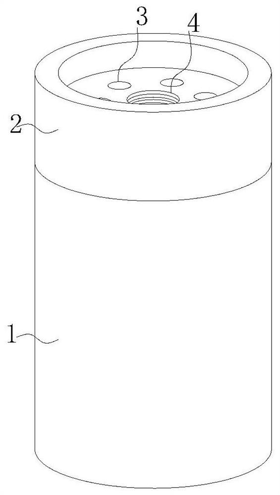
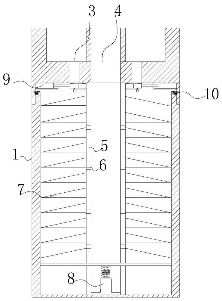
The invention relates to the technical field of filters, in particular to an environment-friendly oil filter which comprises a shell, the outer surface of the upper end of the shell is in threaded connection with a cover body, and an oil outlet is formed in the middle of the outer surface of the upper end of the cover body in a penetrating mode. According to the engine oil filter disclosed by the invention, a substance which is easily expanded by heating is arranged in a first air bag, and gas which is easily expanded in the first air bag expands by absorbing heat generated by entering engine oil to drive the first air bag to expand, so that a first push rod is pushed to move forwards, and the first push rod drives a filter plate to move to an oil inlet; the filter plate is arranged to filter large-particle impurities in engine oil entering from the oil inlet, so that the impurities in the engine oil can be filtered in a classified manner on the whole, an engine oil filter using single microporous filter paper as a filter material is avoided, the filter burden of the filter paper is reduced, the possibility of blockage in the shell is reduced, the service life of the oil filter is prolonged, and the overall practicability is improved.

Description

technical field [0001] The invention relates to the technical field of filters, in particular to an environment-friendly engine oil filter. Background technique [0002] Engine oil filter means to ensure the quality of the engine oil in addition to filtration, such as viscosity, acid value, antioxidant content, etc. These indicators will deteriorate under long-term high-temperature operating environments, so the vehicle should change the engine oil regularly to ensure that the indicators are within within the acceptable range. If the oil does not go through the oil filter and directly enters the lubricating oil circuit, the sundries contained in the oil will be brought to the friction surface of the moving pair, which will accelerate the wear of the parts and reduce the service life of the engine. The function of the oil filter is to filter out sundries, colloids and water in the oil, and deliver clean oil to each lubricating part. During the working process of the engine, ...

Claims


Application Information

Patent Timeline
Patent Type & Authority Applications(China)
IPC IPC(8): F01M11/03F01M11/00F01M11/04
CPCF01M11/03F01M11/00F01M11/04
Inventor 严敏王任威
Owner 严敏
Learn More