
Fault indicator based on power grid engineering

A fault indicator and engineering technology, applied in fault location, fault detection by conductor type, components of electrical measuring instruments, etc., can solve the problems of lateral sliding of high-voltage wires, poor stability of high-voltage wires, troublesome installation and disassembly, etc. Improve installation stability, extend service life, and prevent lateral sliding

Inactive Publication Date: 2021-10-08
许薇
View PDF0 Cites 0 Cited by
  • Summary
  • Abstract
  • Description
  • Claims
  • Application Information

AI Technical Summary

Problems solved by technology

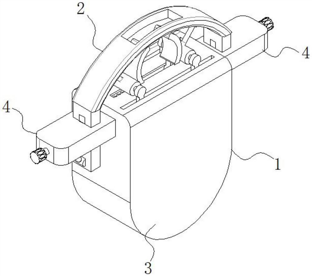
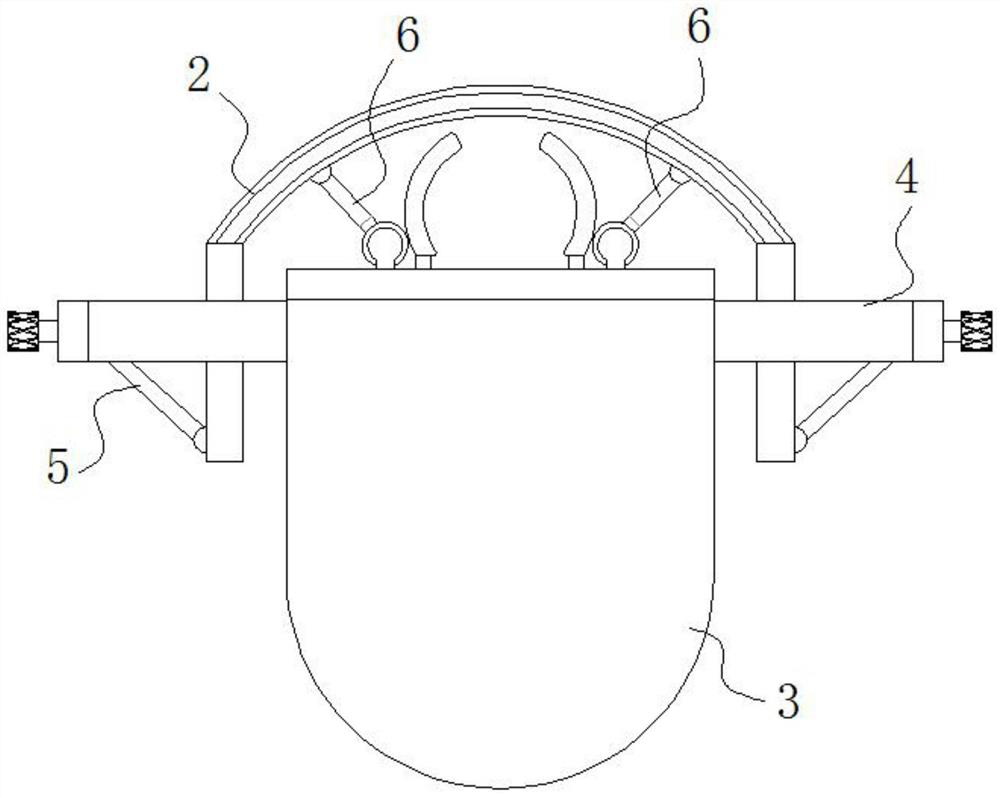
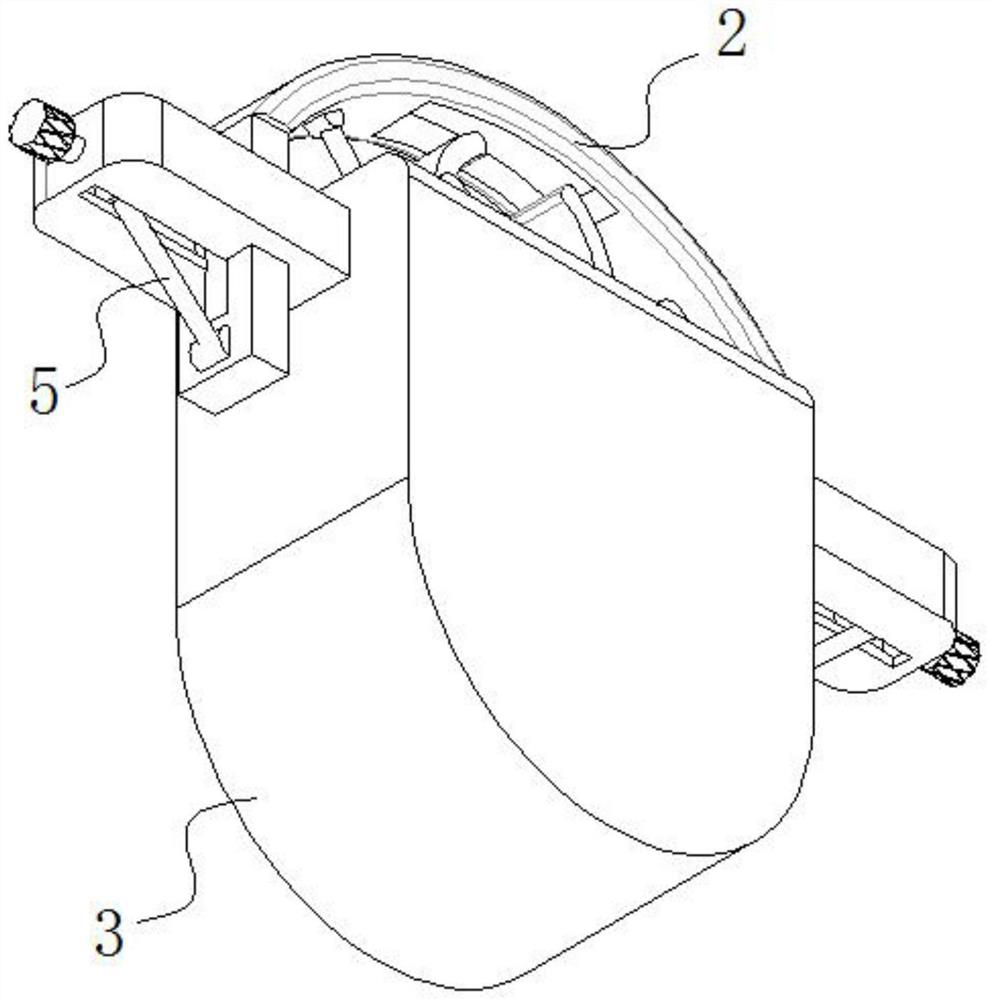
[0004] The purpose of the present invention is to provide a fault indicator based on power grid engineering. Through the design of positioning mechanism, suspension assembly, positioning assembly, adjustment assembly, adjustment rod and push-pull rod, the existing fault indicator is suspended on the high-voltage wire. When the high-voltage wires are prone to lateral sliding, the installation stability of the high-voltage wires is poor, and the existing fault indicators have a single function, which is not convenient for clamping and fixing high-voltage wires of different diameters, thereby greatly reducing the fault indicators. The scope of application of the existing fault indicators is complicated, and the installation and disassembly are very troublesome, resulting in the problem of low disassembly efficiency

Method used


Image

  • Fault indicator based on power grid engineering
  • Fault indicator based on power grid engineering
  • Fault indicator based on power grid engineering

Examples


Embodiment Construction

[0040] The following will clearly and completely describe the technical solutions in the embodiments of the present invention with reference to the accompanying drawings in the embodiments of the present invention. Obviously, the described embodiments are only some, not all, embodiments of the present invention. Based on the embodiments of the present invention, all other embodiments obtained by persons of ordinary skill in the art without creative efforts fall within the protection scope of the present invention.

[0041] see Figure 1-11 , the present invention is a fault indicator based on power grid engineering, including a positioning mechanism 1 and a suspension assembly 2, through which the fault indicator can be suspended on a high-voltage wire;

[0042] The positioning mechanism 1 includes a positioning component 3, and the opposite sides of the positioning component 3 are fixedly connected with the adjustment component 4; the suspension component 2 can be moved up an...


PUM


Abstract

The invention discloses a fault indicator based on a power grid engineering, and relates to the technical field related to a power grid. The fault indicator comprises a positioning mechanism and a hanging assembly, the positioning mechanism comprises a positioning assembly, and adjusting assemblies are fixedly connected to the two opposite side faces of the positioning assembly. The hanging assembly is located at the top of the positioning mechanism and is in sliding connection with the adjusting assembly. An adjusting rod is arranged between the adjusting assembly and the hanging assembly, and a push-pull rod is arranged between the hanging assembly and the positioning assembly. According to the invention, an arc-shaped suspension member is moved up and down, the push-pull rod is utilized to push a positioning column to move horizontally, and the distance between the two wire clamping arc-shaped plates is flexibly adjusted under the combined action of a reset elastic member and the positioning column, so that on one hand, the high-voltage wires with different diameters can be clamped and fixed, and on the other hand, the high-voltage wires can be limited, the transverse sliding of the high-voltage wires is effectively prevented, and the installation stability of the fault indicator is greatly improved.

Description

technical field [0001] The invention belongs to the technical field related to power grids, in particular to a fault indicator based on power grid engineering. Background technique [0002] A fault indicator is an intelligent device installed on a power line for online detection and indication of circuit and single-phase ground faults, helping people find fault points. The fault indicator uses the principle of electromagnetic induction. When the line fails, it will pass the fault current. When the fault current reaches the tower where the indicator is installed, the fault indicator will induce the fault current through the internal electromagnetic coil to generate a mechanical transmission flip sign. In this way, the indication of the faulty section is realized. The traditional fault indicator is suspended on the outdoor overhead high-voltage wire through the clamping assembly. The clamping assembly basically consists of two pressing springs hingedly installed on the lower ...

Claims


Application Information

Patent Timeline
Patent Type & Authority Applications(China)
IPC IPC(8): G01R31/08G01R1/04
CPCG01R31/086G01R1/0425Y04S10/52
Inventor 许薇
Owner 许薇
Learn More