Draw texturing machine

A processing machine and false twisting technology, applied to spinning machines, continuous winding spinning machines, textiles and papermaking, etc., can solve the problem of yarn winding on rotating parts, failure of yarn hanging operation, difficulty of yarn hanging operation, etc. question

Pending Publication Date: 2021-10-12
TMT MACHINERY INC
View PDF0 Cites 0 Cited by
  • Summary
  • Abstract
  • Description
  • Claims
  • Application Information

AI Technical Summary

Problems solved by technology

At this time, if the rotating parts (rollers, discs, endless belts, etc.) of the upper twisting device are already rotating, the yarn will swing under the influence of the wind generated by the rotating parts. job failed
Also, if the yarn is broken during the operation of the false twisting machine, there is a concern that the broken yarn will be wound on the rotating parts

Method used


Image

  • Draw texturing machine
  • Draw texturing machine
  • Draw texturing machine

Examples


Embodiment Construction

[0043] Embodiments of the present invention will be described below with reference to the drawings.

[0044] (Overall structure of false twist processing machine)

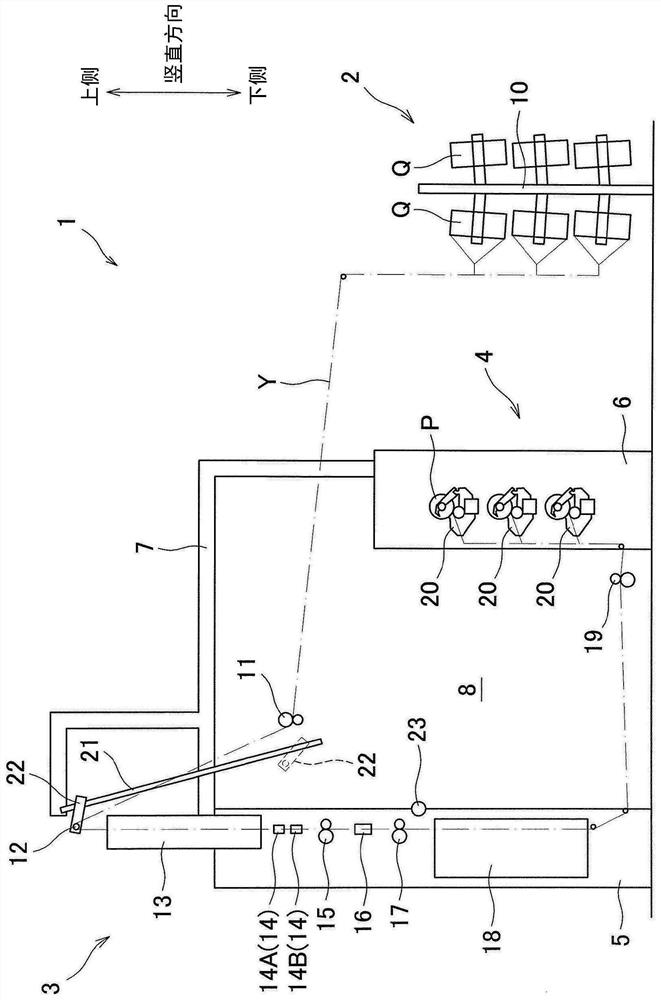
[0045] figure 1 It is an overall configuration diagram of the false twist processing machine 1 according to this embodiment. Such as figure 1 As shown, a false twist processing machine 1 has a yarn supply section 2 that supplies a plurality of yarns Y, a processing section 3 that performs false twist processing on a plurality of yarns Y supplied from the yarn supply section 2, and a false twist processing section 3 that is processed. A plurality of twisted yarns Y are wound to form a winding section 4 of a plurality of packages P.

[0046] The yarn supply unit 2 has a creel 10 holding a plurality of yarn supply packages Q, and supplies a plurality of yarns Y to the processing unit 3 . In the processing section 3, the first yarn feeding roller 11, the anti-twist yarn guide 12, the first heating device 13, the ...


PUM


Abstract

Objects of the present invention are, firstly, to facilitate yarn threading and, secondly, to suppress an unintentional winding of yarns around rotating members at the time of yarn breakage in a draw texturing machine in which plural twisting units are provided on plural stages. In a draw texturing machine comprising plural twisting units 14 each of which includes rotating members 45 to 48 rotated at the time of twisting a yarn Y and which are aligned in a predetermined arrangement direction and provided on plural stages, a partition 60 is provided between a yarn path of the yarn Y passing one twisting unit 14A (or 14B) on one of the plural stages and the rotating members 45 to 48 of one twisting unit 14B (or 14A) which is provided on another stage of the plural stages and which is close to the yarn path.

Description

technical field [0001] The present invention relates to a false twisting machine in which a plurality of twisting devices for twisting yarns are arranged in a predetermined alignment direction and arranged in multiple layers. Background technique [0002] There is currently known a false twist processing machine in which a plurality of twisting devices for twisting yarns are arranged in a predetermined arrangement direction and divided into multiple layers as described in, for example, Patent Document 1 (refer to Patent Document 1). image 3 and Figure 4 ). By arranging the twisting devices in multiple layers, many twisting devices can be arranged in the arrangement direction. [0003] As the twisting device, needle-type, friction-type, and belt-type twisting devices are widely known. The needle twisting device has a plurality of rollers and cylindrical needles in contact with the peripheral surfaces of the plurality of rollers. Then, the needle is rotated by rotating th...

Claims


Application Information

Patent Timeline
Patent Type & Authority Applications(China)
IPC IPC(8): D01H1/11
CPCD01H1/11D02G1/0266D02G1/082D02G1/04D02G1/06D02G1/0273D01H7/923D01H13/045
Inventor 今中昭仁近田秀和
Owner TMT MACHINERY INC
Why Eureka
Try Eureka