
Pivot bearing for steering system

A swing bearing and steering system technology, applied in the field of steering systems, can solve problems such as limited swing range and unpopularity, and achieve the effects of eliminating structural gaps, convenient swing, vibration and noise suppression

Active Publication Date: 2021-06-15
SCHAEFFLER TECH AG & CO KG
View PDF7 Cites 0 Cited by
  • Summary
  • Abstract
  • Description
  • Claims
  • Application Information

AI Technical Summary

Problems solved by technology

[0005] However, the known solutions have the disadvantage that the swivel range is severely limited or that undesired noises can occur in the application due to excessive play

Method used


Image

  • Pivot bearing for steering system
  • Pivot bearing for steering system
  • Pivot bearing for steering system

Examples


Embodiment Construction

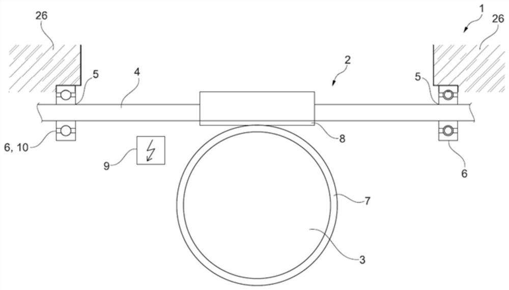
[0025] figure 1 An exemplary embodiment of a steering system 1 with pivot bearing 6 according to the invention is shown. The steering system has a worm gear 2 via which the steering torque is transmitted from a worm shaft 4 to a worm wheel 3 . For this purpose, a toothing 7 is formed on the worm wheel 3 , which meshes with the toothing section 8 of the worm shaft 4 . The worm shaft 4 is mounted in the housing 26 of the worm gear 2 on bearing points 5 , preferably on at least two bearing points 5 . The worm shaft 4 is supported by means of the swivel bearing 6 . The steering system 1 is preferably designed as an electric power steering system 1 . For this purpose, the steering system 1 includes an electric power steering 9 , by means of which the driver's steering force is assisted in order to change the steering angle.

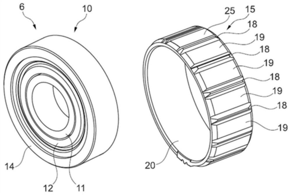
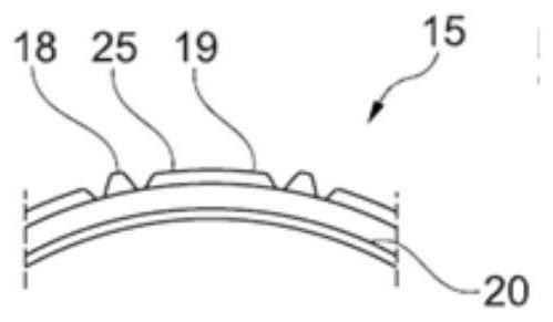
[0026] figure 2 An inventive swivel bearing 6 with a tolerance ring 15 is shown for the steering system 1 . The swivel bearing 6 is designed as a rolli...


PUM


Abstract

The invention relates to a pivot bearing (6) for supporting a worm shaft (4) of a steering system (1), comprising an inner ring (11) and an outer ring (12), a plurality of rolling elements (13) being arranged between the inner ring (12) and the outer ring (12), and comprising a pivot ring (14) in which the outer ring (12) is pivotally received. The pivot ring (14) is received in a tolerance ring (15), with preloading elements (18, 19) being formed on an outer surface of the tolerance ring (15). The invention also relates to a steering system (1) having a pivot bearing (6) of this type.

Description

technical field [0001] The invention relates to a pivot bearing for supporting a worm shaft of a steering system, and to a steering system equipped with such a pivot bearing. [0002] Modern motor vehicles use a steering system to reduce the driver's steering action through the corresponding power steering device. This is known to be possible by hydraulic servo steering or by electric or electrohydraulic steering assistance. Furthermore, steering systems are known which generate a steering torque on the vehicle side and thus prompt the driver of the motor vehicle to adopt a recommended steering movement. In the case of electrically assisted steering systems, a drive motor is generally used, which acts on the worm shaft via a worm gear to generate a correspondingly high steering torque for turning the wheels. [0003] In the solution known from the prior art, the worm shaft is supported in the housing on the side facing the drive shaft via a first rolling bearing, which is de...

Claims


Application Information

Patent Timeline
Patent Type & Authority Applications(China)
IPC IPC(8): F16C23/04F16C35/02F16C35/077F16C27/02F16C27/04
CPCF16C23/043F16C23/045F16C35/02F16C35/077F16C27/02F16C27/04F16C2326/24
Inventor 塞瑞亚斯·穆罕默德尤尔根·格布哈特
Owner SCHAEFFLER TECH AG & CO KG
Learn More