Eureka AIR delivers breakthrough ideas for toughest innovation challenges, trusted by R&D personnel around the world.

Automatic shearing device for sewing residual threads and gas transmission structure thereof

A technology of cutting device and residual thread, which is applied in the sewing machine to cut off the thread mechanism, sewing equipment, sewing machine components, etc. It can solve the problem of low production efficiency, difficulty in controlling and ensuring quality stability, and inability to effectively reduce labor costs. and other issues, to achieve the effect of saving setting costs, economical use efficiency, and short wire ends

Active Publication Date: 2021-10-12
KORIN CO LTD
View PDF6 Cites 0 Cited by
  • Summary
  • Abstract
  • Description
  • Claims
  • Application Information

AI Technical Summary

Problems solved by technology

[0004]However, the existing processing methods for sewing residual threads require a large amount of manpower to carry out operations, resulting in the inability to effectively reduce labor costs; The operation method also appears to be quite low in production efficiency, and the stability of quality is even more difficult to control and ensure

Method used


Image

  • Automatic shearing device for sewing residual threads and gas transmission structure thereof
  • Automatic shearing device for sewing residual threads and gas transmission structure thereof
  • Automatic shearing device for sewing residual threads and gas transmission structure thereof

Examples


Embodiment Construction

[0054] The detailed description and technical content of the embodiments of the present application are described below with the accompanying drawings. However, the drawings are only provided for reference and illustration, and are not used to limit the embodiments of the present application.

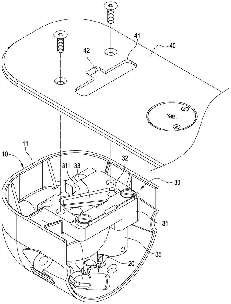
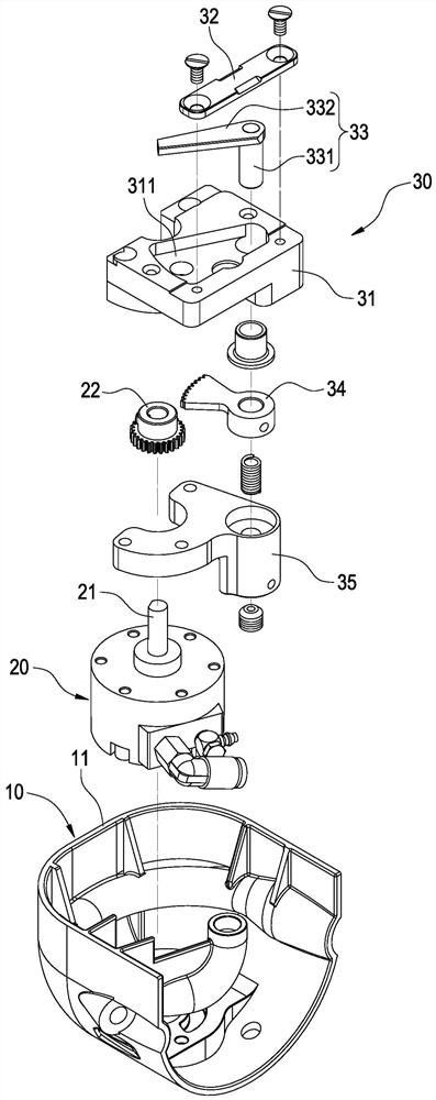
[0055] see Figure 1 to Figure 4 As shown, the embodiment of the present application provides an automatic cutting device for sewing residual thread, which mainly includes an air delivery structure 10 , an actuator 20 and a cutter structure 30 .

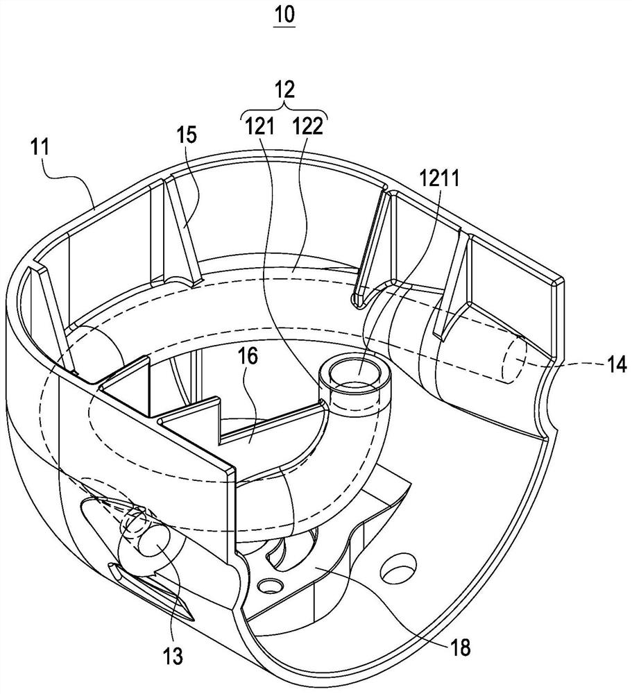
[0056] like image 3 and Figure 4 As shown, the gas transmission structure 10 includes a shell cover 11, which is roughly a U-shaped three-dimensional structure, and an air delivery pipe 12 is arranged inside the shell cover 11. The air delivery pipe 12 mainly includes a suction section 121 and a delivery section 122 connected to the suction section 121. , and at the two side positions of the shell cover 11, there are air intake holes 13 co...


PUM


Abstract

The embodiment of the invention provides an automatic shearing device for sewing residual threads and a gas transmission structure thereof. The automatic shearing device comprises the gas transmission structure, an actuator and a cutter structure; the gas transmission structure comprises a shell cover, and a gas transmission pipe is arranged in the shell cover and comprises a gas suction section and a conveying section; an air inlet hole communicated with the air suction section and the conveying section and an exhaust hole communicated with the conveying section are formed in the shell cover, and a suction inlet is formed in the end, away from the conveying section, of the air suction section; the actuator is fixed in the shell cover; the cutter structure is arranged above the actuator; and the cutter structure comprises a cutter holder, a fixed cutter and a movable cutter matched with the fixed cutter for shearing, wherein the suction inlet is formed below the shearing position of the fixed cutter and the movable cutter. Therefore, the labor operation cost can be saved, and the production efficiency can be improved.

Description

technical field [0001] The present application relates to the technical field of sewing machines, in particular to an automatic cutting device for residual sewing thread and its air delivery structure. Background technique [0002] Sewing machines are distinguished according to the sewing style, which can be roughly divided into two categories: lock stitching (Lock Stitching) and chain stitching (Chain Stitching). On the other hand, at least one needle that holds the needle thread and moves up and down forms a needle loop under the needle plate, and performs the forward and backward movement in a direction approximately perpendicular to the up and down motion path of the needle The advance of the thread hook catches the needle loop, and the captured needle loop is looped with other threads by the hook thread held by the thread hook, thereby forming a chain seam stitch at the sewn part of the cloth. [0003] Among them, chain stitches are mostly used in decorative sewing suc...

Claims


Application Information

Patent Timeline
IPC IPC(8): D05B65/06
CPCD05B65/06
Inventor 林聖智鄭兆閔游仁亨
Owner KORIN CO LTD
Why Eureka
Eureka Blog
Learn More