Supercharge Your Innovation With Domain-Expert AI Agents!

Adapter plate and gear with adapter plate

一种转接板、齿轮的技术,应用在带有齿的元件、皮带/链条/齿轮、齿轮润滑/冷却等方向,能够解决解决方案复杂、安装费力、不能防止渗入等问题,达到防止污染的效果

Pending Publication Date: 2021-10-12
WITTENSTEIN GROUP
View PDF2 Cites 0 Cited by
  • Summary
  • Abstract
  • Description
  • Claims
  • Application Information

AI Technical Summary

Problems solved by technology

However, known solutions identify leaks but do not prevent infiltration especially in installation positions with gears arranged vertically above the motor
BACKGROUND OF THE INVENTION Known solutions, such as those shown in document FR 2622946 A1, are complex and laborious to install

Method used


Image

  • Adapter plate and gear with adapter plate
  • Adapter plate and gear with adapter plate
  • Adapter plate and gear with adapter plate

Examples


Embodiment Construction

[0035] Exemplary embodiments of the present invention will be described below based on the accompanying drawings, wherein the present invention is not limited to the exemplary embodiments, and the scope of the present invention is determined by the claims. In the description of the embodiments, the same reference numerals may be used for the same or similar parts in different drawings and different embodiments in order to clarify the description. However, this does not mean that the corresponding parts of the present invention are limited to the modifications shown in the embodiments.

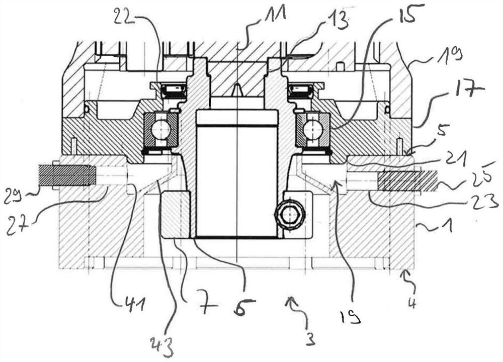
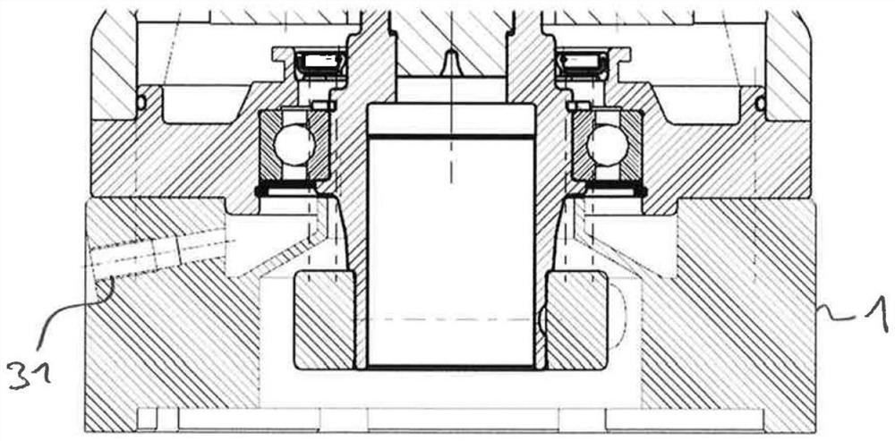
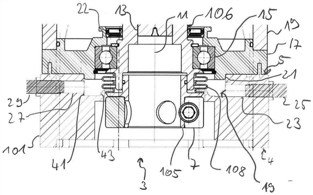
[0036] figure 1 and figure 2 An exemplary embodiment of the adapter plate 1 is shown in two sections which are rotated by 90° about the longitudinal axis of the adapter plate 1 or about the axis of the through-opening of the adapter plate 1 . Therefore, describe together figure 1 and figure 2 . Similarly, this also applies to image 3 and Figure 4, which shows another embodiment. It ...


PUM


Abstract

The invention relates to an adapter plate (1) for connecting a motor and a gear box (19), having a passage opening (3) for receiving a shaft coupling at least partially, a groove (19) arranged in a first front side (5) of the adapter plate (1, 101) and extending circumferentially around the passage opening (3), and at least one channel (23, 27, 31) which is in communication with the groove (19).

Description

technical field [0001] The invention relates to an adapter plate for connecting an electric motor and a gearbox and a method for operating a gear. Background technique [0002] Adapter plates for connecting electric motors and gearboxes are known from the prior art. [0003] In a motor-gear combination, oil or grease seeping from the gear into the motor can cause problems. A seal is provided to avoid this infiltration. [0004] In order to recognize the risk of possible oil penetration when the seal between the electric motor and the gear fails, solutions are known from the prior art, for example, to provide a leak sensor such as that described in document DE 10 2015 105 609 A1. However, known solutions recognize leaks, but do not prevent infiltration, especially in installation positions with gears arranged vertically above the electric motor. BACKGROUND OF THE INVENTION Known solutions, such as those shown in document FR 2622946 A1, are complex and laborious to install....

Claims


Application Information

Patent Timeline
Patent Type & Authority Applications(China)
IPC IPC(8): F16H57/025F16H57/029F16H57/04F16H57/021F16H61/12
CPCF16H57/025F16H57/029F16H57/0405F16H57/045F16H57/0424F16H57/021F16H61/12F16H2061/1208F16H57/031F16H2057/02034H02K7/116F16H57/0449F16H57/0464H02K7/003H02K5/167H02K11/20H02K5/00F16H57/04
Inventor 克里斯托夫·古德莱因霍尔德·库恩
Owner WITTENSTEIN GROUP
Features
  • R&D
  • Intellectual Property
  • Life Sciences
  • Materials
  • Tech Scout
  • Unparalleled Data Quality
  • Higher Quality Content
  • 60% Fewer Hallucinations
Learn More