Flow channel for separating and discharging condensate

A condensate and flow channel technology, applied in the field of flow channels, can solve the problem of condensate reaching the compressor or compactor, compressor impeller damage, etc., and achieve the effect of effective use of structural space

Pending Publication Date: 2020-07-24
FORD GLOBAL TECH LLC
View PDF2 Cites 0 Cited by
  • Summary
  • Abstract
  • Description
  • Claims
  • Application Information

AI Technical Summary

Problems solved by technology

Especially in applications with low pressure exhaust gas return, there is a risk of condensate reaching the compressor or compactor
In this case, the action of condensate droplets on the compressor blades can cause damage to the compressor wheel due to shear forces

Method used


Image

  • Flow channel for separating and discharging condensate
  • Flow channel for separating and discharging condensate
  • Flow channel for separating and discharging condensate

Examples


Embodiment Construction

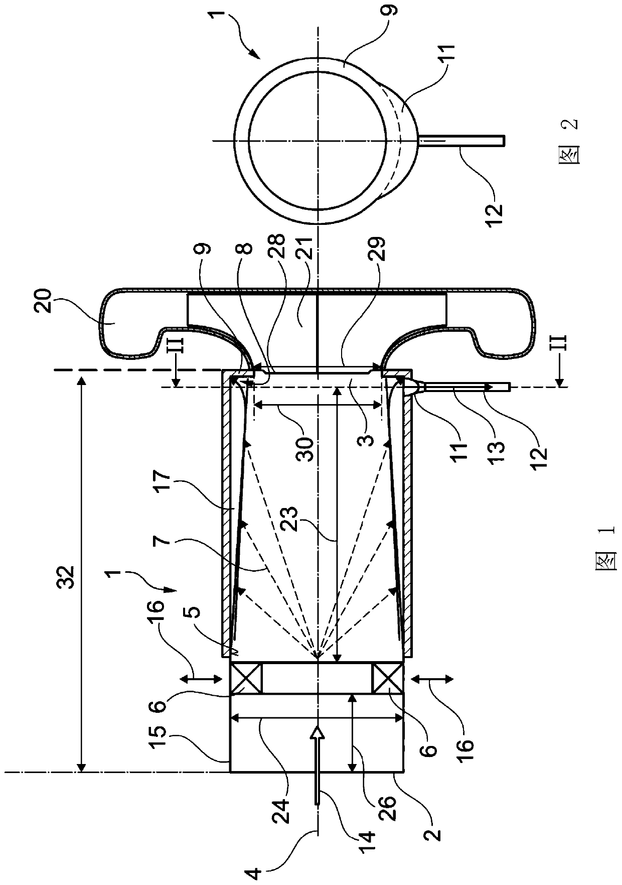
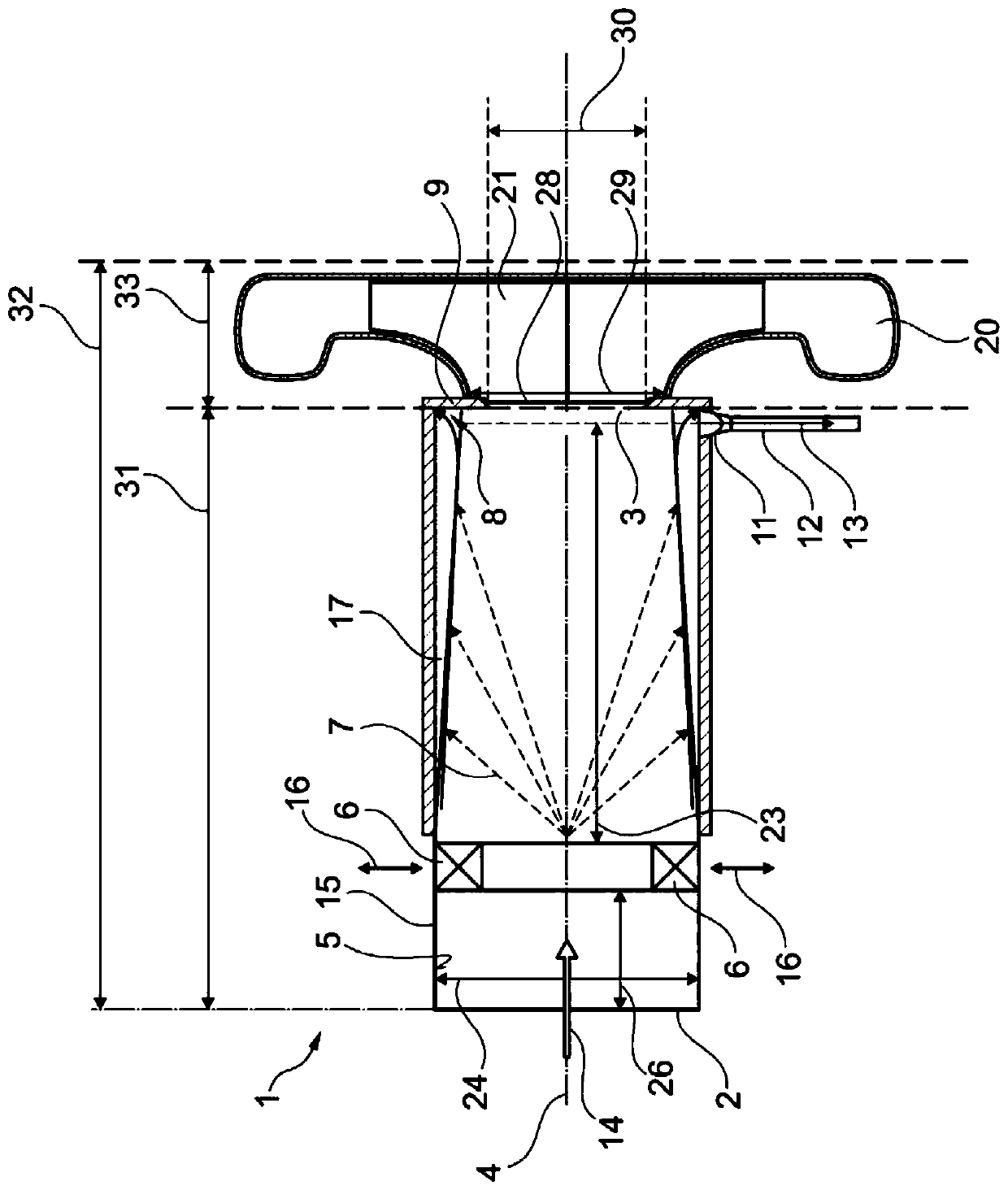
[0027] Figure 1 to Figure 3 The shown flow channel 1 according to the invention comprises an inlet 2 , an outlet 3 and a central axis 4 . In the variant shown, the central axis 4 is both the central axis of the inlet 2 and the central axis of the outlet 2 . As an alternative to the variant shown, the central axes of the inlet 2 and the outlet 3 can also differ from each other, so that the flow channel 1 can also have one or more curves. The flow channel 1 according to the invention also comprises an inner surface 5 and an outer wall 15 .

[0028]At least one turbulence generator 6 is arranged downstream of the inlet 2 and upstream of the outlet 3 . The at least one turbulence generator 6 can be arranged, for example, directly at the inlet 2 or at a distance 26 of less than one third of the length of the flow channel 1 . At least one turbulence generator 6 is displaceable in radial direction. This is indicated by arrow 16 . Thus, at least one turbulence generator 6 can be...


PUM


Abstract

The invention relates to a flow channel for separating and discharging condensate. A flow channel (1) having an inner surface (5), an inlet (2) configured to be technically fluidically connected to anexhaust gas recirculation passage, and an outlet (3) configured to be technically fluidically connected to an inlet of a compressor (20) is described. The flow channel (1) comprises a central axis (4), and at least one turbulence generator (6) is arranged downstream of the inlet (2) and upstream of the outlet (3). The at least one turbulence generator (6) is displaceable in a radial direction (16). A condensate collecting device (8) is arranged on the outlet (3), extends along the periphery of the outlet (3), is defined radially to the outside by the inner surface (5) of the flow channel (1)and is delimited in the axial direction by a collecting edge (9), the condensate collecting device (8) being connected to the outlet (12) in a technical flow manner.

Description

technical field [0001] The present invention relates to flow passages, and more particularly to flow passages for use in conjunction with exhaust return passages and compressors. The invention also relates to a compressor, a turbocharger, an exhaust gas recirculation device, a method for operating an exhaust gas recirculation device, and a motor vehicle. Background technique [0002] In order to achieve the required exhaust emission limit values, exhaust gas recirculation is usually carried out, in particular in combination with various exhaust gas aftertreatment methods, such as the use of lean NOx traps and catalytic converters with selective catalytic reduction. In this case, the high specific humidity in the exhaust gas leads to the formation of large amounts of condensate during cooling of the exhaust gas. Especially in applications with low-pressure exhaust gas return, there is a risk of condensate reaching the compressor or compactor. In this case, the action of the...

Claims


Application Information

Patent Timeline
Patent Type & Authority Applications(China)
IPC IPC(8): F02M26/35F02M26/06F02M26/17
CPCF02M26/06F02M26/17F02M26/35F02M35/0223F02M35/10222F02M35/10262F02M26/50Y02T10/12
Inventor A·库斯克F·A·萨默候夫J·克默林V·斯米利亚诺夫斯基H·M·金德尔H·弗里德里希斯F·克拉默L·赫可曼F·文德利希
Owner FORD GLOBAL TECH LLC
Why Eureka
Try Eureka