A hydraulic oil tank with oil-water separation

A hydraulic oil tank and oil-water separation technology, which is applied in the direction of oil supply tank devices, fluid pressure actuation devices, fluid pressure actuation system components, etc., can solve the problems of oil-water separation, poor effect, and failure

Inactive Publication Date: 2016-12-28
博尔德南通汽车零部件有限公司
View PDF9 Cites 0 Cited by
  • Summary
  • Abstract
  • Description
  • Claims
  • Application Information

AI Technical Summary

Problems solved by technology

Due to the water vapor in the atmosphere, water immersion during storage, transportation, pumping and use, appears in the form of dissolved water, free water and emulsified water in the oil, this phenomenon has caused a huge impact on the stability of the hydraulic system Therefore, a drain valve is installed at the lower part of the fuel tank body. The function of the drain valve is to manually drain the water after the oil-water separation in the fuel tank. However, this drainage method requires a good oil-water separation environment. At present, this kind of fuel tank In the working state, due to the characteristics of the hydraulic system, the oil in the oil return tank is in a violent tumbling state, and the water is always mixed in the oil, which cannot be completely separated from the oil and water, so the effect is not good.

Method used


Image

  • A hydraulic oil tank with oil-water separation
  • A hydraulic oil tank with oil-water separation
  • A hydraulic oil tank with oil-water separation

Examples


Embodiment Construction

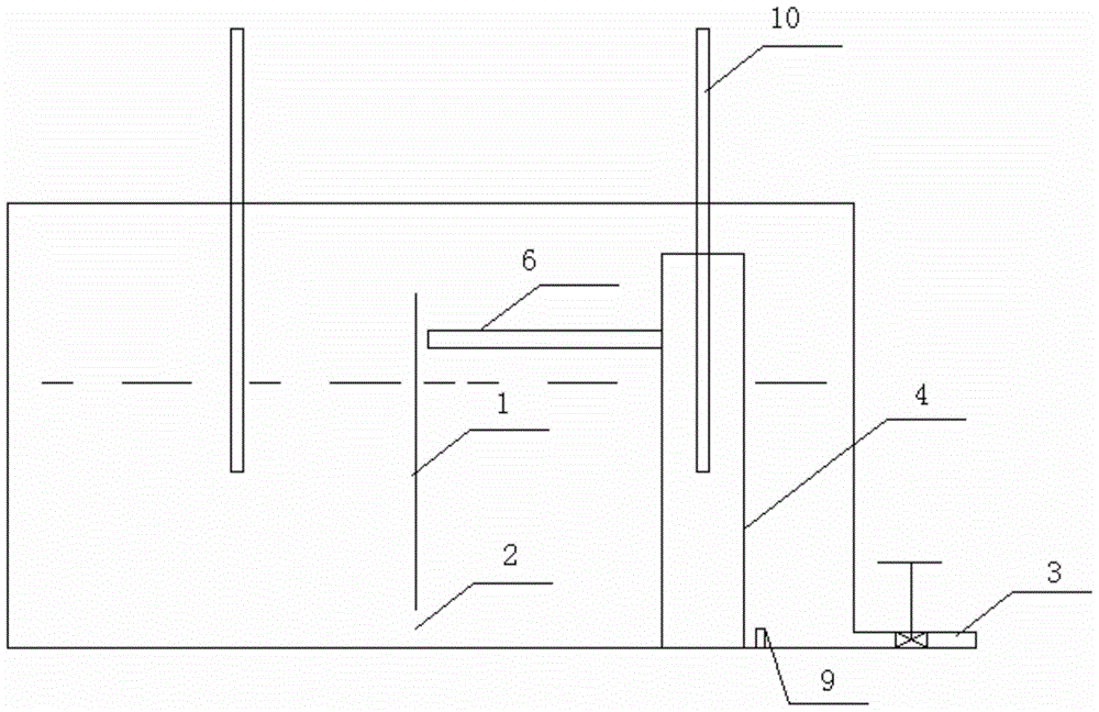
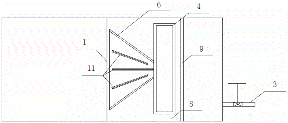
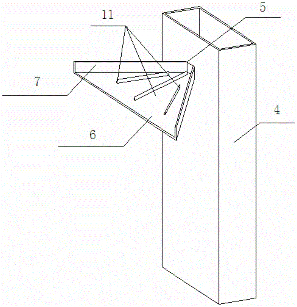
[0010] see figure 1 figure 2 image 3 , when the oil tank is working, different from the prior art, the oil in the oil return pipe 10 does not flow back into the oil return tank, but returns the oil to the oil return barrel 4 of the oil return tank. The oil in the barrel overflows through the opening 5 of the barrel wall and flows into the diffusion device 6. Due to the action of the column edge 7 erected upward along the corner of the welding surface on the diffusion device 6, and at the same time under the action of the diverter bar 11, the inflow is diffused. The oil surface in the device 6 expands into a plane, and the oil speed slows down. When the return oil flows out from the diffusion device 6 and flows downward against the partition 1 without impact, the generation of air bubbles is reduced. The above not only maintains the stability of oil convection, but also reduces the air bubbles on the oil surface, so that oil and water can be separated better. When the retu...


PUM


Abstract

The invention relates to an oil-water separated hydraulic oil tank. An oil-return area is provided with an-oil return barrel, the oil-return barrel is provided with an opening, and the opening is welded with a diffusing device enabling return oil to overflow and uniformly disperse. During the operation of the oil tank, oil in the oil barrel flows to the diffusing device via the opening at a barrel wall, oil liquid is expanded to a plane, and the speed of the oil is reduced; when the return oil flows downwardly to a separating plate from the diffusing device, bubbles are reduced, the convection stability of the oil liquid in the oil-return area is maintained, the oil-return area of the oil-return barrel and a tank body surface opposite to the separating plate is connected with the whole oil-return area, certain cycle is participated in, the liquid level tends to a stationary state, oil and water can be effectively separated in a static manner, and a return-blocking strip arranged at the lower side of the oil-return area blocks water deposited at the bottom of the tank; and when a drainage valve is opened, water can be drained from the drainage valve. According to the oil-water separated hydraulic oil tank, bubbles in the oil liquid entering an oil-suction pipe and a system can be effectively reduced, water in the processes of pumping, injection and usage can be effectively separated, and the stability of the hydraulic system is well improved.

Description

technical field [0001] The invention relates to a circulating oil tank, in particular to a hydraulic oil tank for oil-water separation. Background technique [0002] At present, the oil suction and oil return of the oil tank are the oil inlet and outlet channels of the system. The oil out of the oil suction pipe returns to the tank through the oil return pipe. The oil tank is separated into two parts by the partition, and the height of the partition is higher than the oil liquid level. The air bubbles generated during the oil return process are isolated by the separator and stay on the oil return side of the separator, and the oil without air bubbles flows into the non-bubble side of the separator through the through hole in the lower part of the separator to form the circulation of the oil. This structure can effectively prevent air bubbles in the oil from entering the oil suction pipe and entering the system. Due to the water vapor in the atmosphere, water immersion durin...

Claims


Application Information

Patent Timeline
Patent Type & Authority Patents(China)
IPC IPC(8): F15B1/26F15B21/04
CPCF15B1/26F15B21/044
Inventor 陈伟东
Owner 博尔德南通汽车零部件有限公司
Why Eureka
Try Eureka