
Laser projection device

A technology of laser projection and optical device, applied in the direction of image reproducer, projection device, optics, etc. of the projection device, can solve the problems of increasing product cost, increasing the size of the projector, and large size, and achieves lower production costs and lower production costs. The effect of speckle contrast

Pending Publication Date: 2021-10-12
APPOTRONICS CORP LTD
View PDF0 Cites 0 Cited by
  • Summary
  • Abstract
  • Description
  • Claims
  • Application Information

AI Technical Summary

Problems solved by technology

However, laser projection is a coherent light source, which will produce speckle phenomenon, that is, granular patterns with undulating light and dark, which will affect the viewing experience of the audience.
In the prior art, methods such as wavelength division, rotational averaging, and time coherence reduction are used to reduce speckle contrast, but the wavelength division method has strict requirements on the wavelength selection of the light source, which will greatly increase the product cost; the rotating elements used in the rotational averaging method are generally The volume is large and needs to be driven by a motor, which leads to an increase in the volume of the projector and is prone to noise; reducing time coherence and using materials such as volume diffusion will reduce the light efficiency of the projector

Method used


Image

  • Laser projection device
  • Laser projection device
  • Laser projection device

Examples


Embodiment Construction

[0014] The technical solutions in the embodiments of the present application will be clearly and completely described below with reference to the drawings in the embodiments of the present application. Obviously, the described embodiments are only a part of the embodiments of the present application, but not all of the embodiments. Based on the embodiments in the present application, all other embodiments obtained by those of ordinary skill in the art without creative efforts shall fall within the protection scope of the present application.

[0015] In order to make those skilled in the art better understand the technical solutions of the present application, the laser projection device provided by the invention will be described in further detail below with reference to the accompanying drawings and specific embodiments.

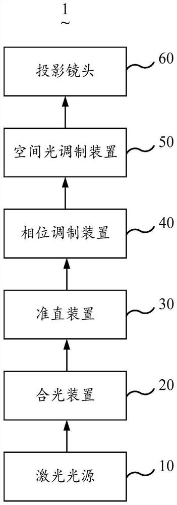
[0016] see figure 1 , figure 1 It is a schematic structural diagram of the first embodiment of the laser projection device of the present application. T...


PUM


Abstract

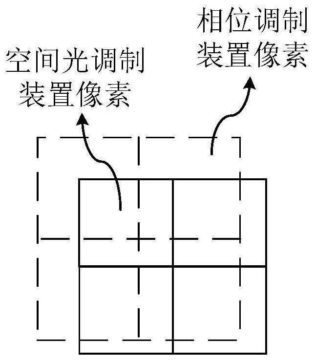
The invention discloses a laser projection device which at least comprises a laser light source, a light combination device, a collimation device, at least one phase modulation device and a spatial light modulation device, and laser generated by the laser light source is irradiated to the phase modulation device through the light combination device and the collimation device. The phase modulation device is used for carrying out phase modulation on the laser, and the spatial light modulation device is used for carrying out optical signal spatial distribution modulation on the laser subjected to phase modulation, wherein one spatial light modulation pixel is covered by at least two phase modulation pixels. According to the application, the phase modulation device is added, the laser beam generated by the laser light source is subjected to phase modulation, and meanwhile, one spatial light modulation pixel is covered by at least two phase modulation pixels, so that the same pixel of the spatial light modulation device is influenced by pixel phases of a plurality of phase modulation devices, the average light intensity is realized, and the speckle contrast ratio is reduced.

Description

technical field [0001] The present application relates to the field of laser display, and in particular, to a laser projection device. Background technique [0002] Laser projection displays are becoming more and more popular with audiences due to their high brightness and large color gamut. However, laser projection is a coherent light source, which will produce speckle, a granular pattern of undulating light and dark, which affects the viewing experience of the audience. In the prior art, methods such as wavelength division, rotational averaging, and temporal coherence reduction are used to reduce speckle contrast. However, the wavelength division method has stricter requirements on the wavelength selection of the light source, which will greatly increase the cost of the product; the rotating elements used in the rotational averaging method are commonly used. The size of the projector is large, and it needs to be driven by a motor, which leads to an increase in the size o...

Claims


Application Information

Patent Timeline
Patent Type & Authority Applications(China)
IPC IPC(8): G03B21/20G02B27/10H04N9/31
CPCG03B21/2033G03B21/206G02B27/1006H04N9/315H04N9/3102G02B27/10G03B21/20H04N9/31G03B21/14
Inventor 李士杰王霖贾坤李屹
Owner APPOTRONICS CORP LTD
Learn More