LED down lamp

A technology of LED downlights and LED lamps, which is applied in lighting and heating equipment, point light sources, lighting devices, etc., can solve the problems of increasing the weight of downlights, unsightly appearance, and inability to heat curved gardens, etc., and achieves convenient use and transparency Good light effect, easy to make effect

Inactive Publication Date: 2015-08-26
SPIMAGE XIAMEN CO LTD
View PDF7 Cites 0 Cited by
  • Summary
  • Abstract
  • Description
  • Claims
  • Application Information

AI Technical Summary

Problems solved by technology

[0002] LED is a green energy-saving light source with high light conversion efficiency and has been widely used for lighting. Due to the low voltage of LED itself, it must be converted into low-voltage drive by an external switching power supply when used in combination with mains power. Usually, it is reflected in downlight products. It is a very inconvenient and unsightly state, and increases the weight of the downlight itself, which has potential safety risks, and also involves a variety of cost increases in packaging costs, transportation costs, and installation costs
[0003] Various light-transmitting plates are installed on the existing LED lamps. This light-transmitting plate includes acrylic, polycarbonate, and artificial stone plates made of unsaturated polyester resin. This artificial stone The thickness of the similar plate is 5mm, and the length and width are about 1-2m. This kind of artificial stone can be installed with a background light on its back, and the light can penetrate from the back. The production of this light-transmitting plate was first inspired by natural hibiscus stone , because this natural stone has been used to make a variety of stone lamps, and the light can come out from the inside of the stone, but this kind of stone is very expensive and cannot heat the curved garden.

Method used


Image

  • LED down lamp

Examples


Embodiment 1

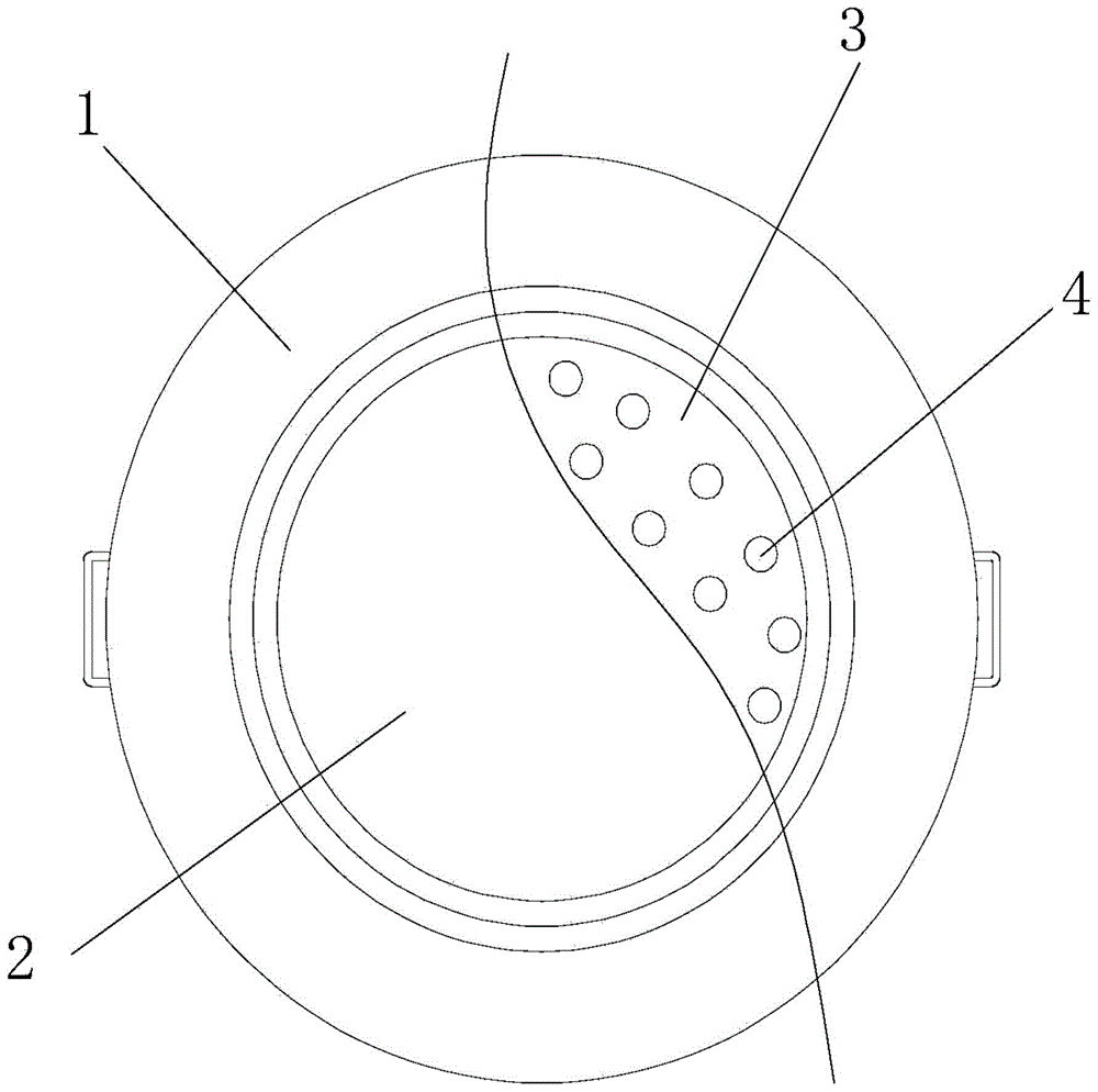
[0021] see figure 1 , in an embodiment of the present invention, an LED downlight includes an LED downlight body 1, a light-transmitting plate 2, a driving circuit board 3, an LED lamp 4 and a built-in driving power supply circuit, and the light-transmitting plate 2 is installed on the LED downlight On the light outlet of the main body 1, the LED driving circuit board 3 is installed in the accommodation space between the LED downlight main body 1 and the light-transmitting plate 2, and the LED lamp 4 is packaged on the LED driving circuit board 3 and connected with the LED driving circuit board 3. The circuit board 3 is electrically connected, and the LED driving circuit board 3 is provided with a built-in driving power circuit, and the built-in driving power circuit is electrically connected with the LED lamp 4, so that the LED light source part and the power driving part are designed in one, and the light-transmitting The raw materials of board 2 according to parts by weight...

Embodiment 2

[0031] see figure 1 , in an embodiment of the present invention, an LED downlight includes an LED downlight body 1, a light-transmitting plate 2, a driving circuit board 3, an LED lamp 4 and a built-in driving power supply circuit, and the light-transmitting plate 2 is installed on the LED downlight On the light outlet of the main body 1, the LED driving circuit board 3 is installed in the accommodation space between the LED downlight main body 1 and the light-transmitting plate 2, and the LED lamp 4 is packaged on the LED driving circuit board 3 and connected with the LED driving circuit board 3. The circuit board 3 is electrically connected, and the LED driving circuit board 3 is provided with a built-in driving power circuit, and the built-in driving power circuit is electrically connected with the LED lamp 4, so that the LED light source part and the power driving part are designed in one, and the light-transmitting The raw materials of board 2 include: 90 parts of polymer...

Embodiment 3

[0041] see figure 1 , in an embodiment of the present invention, an LED downlight includes an LED downlight body 1, a light-transmitting plate 2, a driving circuit board 3, an LED lamp 4 and a built-in driving power supply circuit, and the light-transmitting plate 2 is installed on the LED downlight On the light outlet of the main body 1, the LED driving circuit board 3 is installed in the accommodation space between the LED downlight main body 1 and the light-transmitting plate 2, and the LED lamp 4 is packaged on the LED driving circuit board 3 and connected with the LED driving circuit board 3. The circuit board 3 is electrically connected, and the LED driving circuit board 3 is provided with a built-in driving power circuit, and the built-in driving power circuit is electrically connected with the LED lamp 4, so that the LED light source part and the power driving part are designed in one, and the light-transmitting The raw materials of board 2 according to parts by weight...


PUM


Abstract

The invention discloses an LED down lamp. The LED down lamp comprises an LED (light-emitting diode) down lamp body, a light-transmitting plate, a driving circuit board, an LED lamp and a built-in driving power supply circuit, wherein the light-transmitting plate is installed on the light outlet of the LED down lamp body; the LED driving circuit board is installed in the accommodating space between the LED down lamp body and the light-transmitting plate; raw materials of the light-transmitting plate (in parts by weight) include a polymer resin, an ABS resin, a fire-resistant master batch, a curing agent, aluminum hydroxide, an accelerator, a nanometer powder, a polyester mill base (yellow), a polyester mill base (red), vinyl benzene, titanium dioxide, a compound lubricant and an anti-foaming agent. The LED down lamp is characterized in that the built-in driving power supply circuit is arranged on the LED driving circuit board, so that the LED light source part and the power supply driving part are integrally designed, the LED down lamp cannot be affected on light effect, is relatively simple and beautiful, and is relatively convenient to install and use by an user; the light-transmitting plate for decorating the LED is good in light-transmitting effect, beautiful in appearance and convenient to manufacture, and thus the light-transmitting plate can be widely applied to irregular decorative lighting, lamp posts, and diaphanous cylinder lighting ceilings.

Description

technical field [0001] The invention relates to an LED lamp, in particular to an LED downlight. Background technique [0002] LED is a green energy-saving light source with high light conversion efficiency and has been widely used for lighting. Due to the low voltage of LED itself, it must be converted into low-voltage drive by an external switching power supply when used in combination with mains power. Usually, it is reflected in downlight products. It is a very inconvenient and unattractive state, and increases the weight of the downlight itself, which has potential safety risks, and also involves various increases in packaging costs, transportation costs, and installation costs. [0003] Various light-transmitting plates are installed on the existing LED lamps. This light-transmitting plate includes acrylic, polycarbonate, and artificial stone plates made of unsaturated polyester resin. This artificial stone The thickness of the similar plate is 5mm, and the length and ...

Claims


Application Information

Patent Timeline
Patent Type & Authority Applications(China)
IPC IPC(8): F21S8/00F21V5/00F21V23/00F21Y101/02
CPCF21S8/00F21V5/00F21V23/003
Inventor 潘小和
Owner SPIMAGE XIAMEN CO LTD
Why Eureka
Try Eureka