Toughened glass transportation device with anti-fragmentation structure

A tempered glass and transportation device technology, which is applied in transportation and packaging, multi-axis trolleys, trolley accessories, etc., can solve the problems of non-layered placement structure, poor shock absorption performance, and inadequate treatment of tempered glass protection, reducing the need for The effect of bumping amplitude, convenient loading and unloading, and avoiding damage

Pending Publication Date: 2021-10-15
吴艳霞
View PDF0 Cites 1 Cited by
  • Summary
  • Abstract
  • Description
  • Claims
  • Application Information

AI Technical Summary

Problems solved by technology

[0003] The object of the present invention is to provide a tempered glass transportation device with an anti-shatter structure, to solve the problem of the poor shock absorption performance of the existing transportation device proposed in the above-mentioned background technology, and the non-layered placement structure, which protects the tempered glass Not in place

Method used


Image

  • Toughened glass transportation device with anti-fragmentation structure
  • Toughened glass transportation device with anti-fragmentation structure
  • Toughened glass transportation device with anti-fragmentation structure

Examples


Embodiment 1

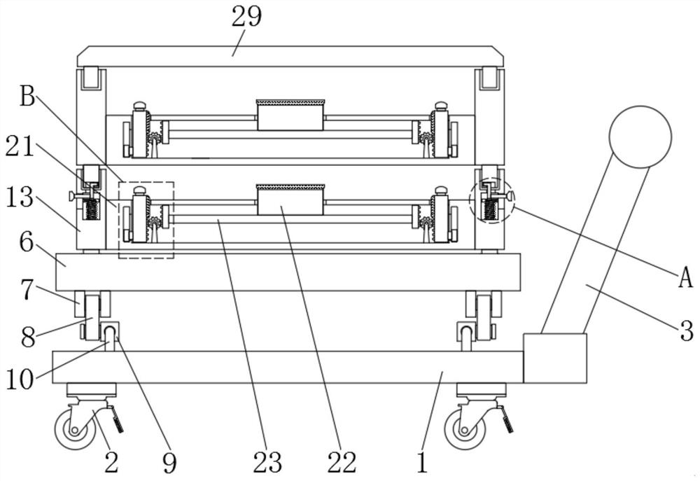
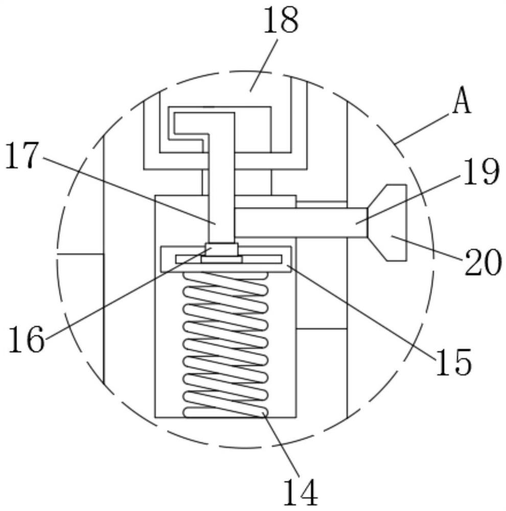
[0030] see Figure 1-7 , an embodiment provided by the present invention: a tempered glass transportation device with an anti-shatter structure, including a base plate 1, universal wheels 2 are fixedly installed around the lower end of the base plate 1, and a drag handle is fixedly installed on the right side of the base plate 1. The rod 3 and the left and right groups of the bottom plate 1 are all fixedly equipped with a cover plate 4, and the upper end of the cover plate 4 is sleeved with a limit plate 5, and the limit plate 5 is movably plugged into the inside of the cover plate 4, where the load-bearing plate can be adjusted. 6 to limit the position, thereby improving the overall stability of the device, the upper end of the limit plate 5 is fixedly installed on the bottom end of the load-bearing plate 6, and the bottom end of the load-bearing plate 6 is fixedly installed with a connecting block 7, and the side of the connecting block 7 is connected to the The rod 8 is hin...

Embodiment 2

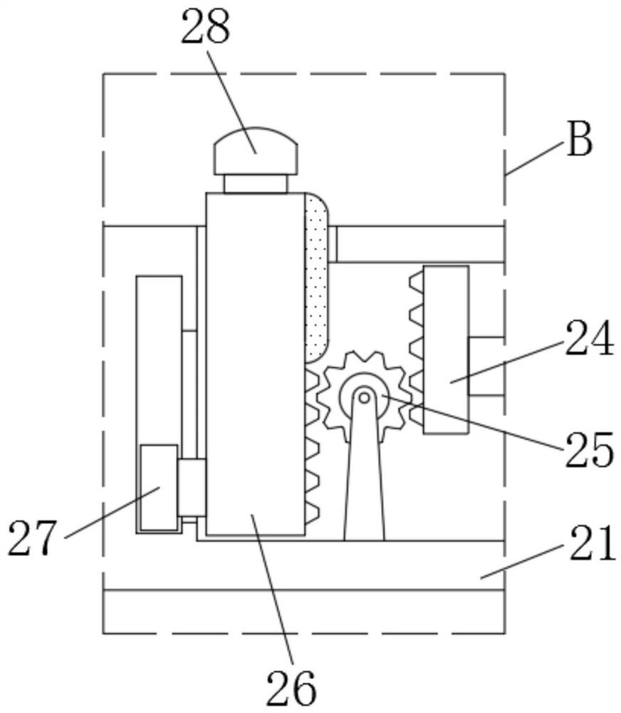
[0036] In this example, if Figure 8 As shown, the bottom of the depression bar 23 is connected with the same balance plate 30, the bottom of the placement plate 21 is provided with a first air bag 31 in the cavity, and the side of the splint 26 towards the notch is provided with a second air bag 32, the second air bag 32 is positioned above the upper surface of the placement plate all the time, and the first airbag 31 communicates with the second airbag 32 through the vent pipe 33. During use, when the tempered glass is placed on the placing plate 21, the pressing plate 22 moves downward, on the one hand, the clamping plate 26 is driven up by the pressing bar 23, the second connecting plate 24 and the gear 25, and on the other hand, the pressing plate 22 moves downward. While moving, the balance board 30 moves downwards and presses on the first air bag 31, and the first air bag 31 inflates the second air bag 32 arranged on the splint 26 through the vent pipe 33, and now the s...


PUM


Abstract

The invention relates to the technical field of tempered glass transportation, in particular to a tempered glass transportation device with an anti-fragmentation structure, which comprises a bottom plate, universal wheels are mounted on the periphery of the lower end of the bottom plate, a towing rod is mounted on the right side of the bottom plate, sleeve plates are fixedly mounted on the left and right groups of the bottom plate, and a gear is connected to one side, away from a pressing rod, of a second connecting plate. A clamping plate is connected to the side, away from the second connecting plate, of the gear, a sliding block is fixedly mounted on the side, away from the gear, of the clamping plate, a button is arranged at the top end of the clamping plate, and a cover plate is mounted at the top end of the mounting frame. According to the transportation device, first springs and a buffer plate are arranged, when a vehicle bumps, the first springs and the buffer plate generate elastic deformation, a certain buffer space can be provided between the bottom plate and the bearing plate through mutual cooperation of a connecting sleeve, a connecting rod and a bearing rod, and therefore the bump amplitude of the transport device is effectively reduced, and the toughened glass is buffered and protected.

Description

technical field [0001] The invention relates to the field of tempered glass transportation, in particular to a tempered glass transportation device with an anti-shatter structure. Background technique [0002] Tempered glass needs to be stored centrally after production, which involves the transportation of tempered glass. However, there are still many deficiencies in the existing transportation devices. First, most of the existing transportation devices for tempered glass have relatively simple structures. The protective treatment measures for tempered glass are not in place, and the shock absorption performance is relatively general. During the transportation process, large vibrations will still be generated, which will cause the tempered glass to shatter. On the other hand, the existing transportation device has no layered placement structure. When loading, the glass is often stacked and stacked. When the quantity of transported glass is large, it is easy to cause the low...

Claims


Application Information

Patent Timeline
Patent Type & Authority Applications(China)
IPC IPC(8): B62B3/04B62B5/00
CPCB62B5/0006B62B3/04B62B2203/44
Inventor 吴艳霞
Owner 吴艳霞
Why Eureka
Try Eureka