
Lifting structure for building construction

A lifting structure and building construction technology, applied in the direction of building structure, building, housing structure support, etc., can solve the problems of low construction efficiency, poor stability of step ladders, limited standing and construction space, etc., to achieve simple and convenient operation, reduce Production and use costs, the effect of high safety factor

Active Publication Date: 2021-10-15
湖南玖环建设工程有限公司
View PDF5 Cites 0 Cited by
  • Summary
  • Abstract
  • Description
  • Claims
  • Application Information

AI Technical Summary

Problems solved by technology

[0003] It is often necessary to use a lifting structure at the construction site to carry out construction on the surface of the building at different heights. The current lifting mechanism often uses a step ladder, but the step ladder is often poor in stability. Construction workers stand and walk on the step ladder. The construction space is limited, falling accidents are prone to occur, and the construction efficiency is also very low, and the step ladder cannot satisfy the construction workers for placing and picking up various construction tools

Method used


Image

  • Lifting structure for building construction
  • Lifting structure for building construction
  • Lifting structure for building construction

Examples


Embodiment Construction

[0024] In order to make the above objects, features and advantages of the present invention more comprehensible, specific implementations of the present invention will be described in detail below in conjunction with the accompanying drawings. In the following description, numerous specific details are set forth in order to provide a thorough understanding of the present invention. However, the present invention can be implemented in many other ways different from those described here, and those skilled in the art can make similar improvements without departing from the connotation of the present invention, so the present invention is not limited by the specific implementations disclosed below.

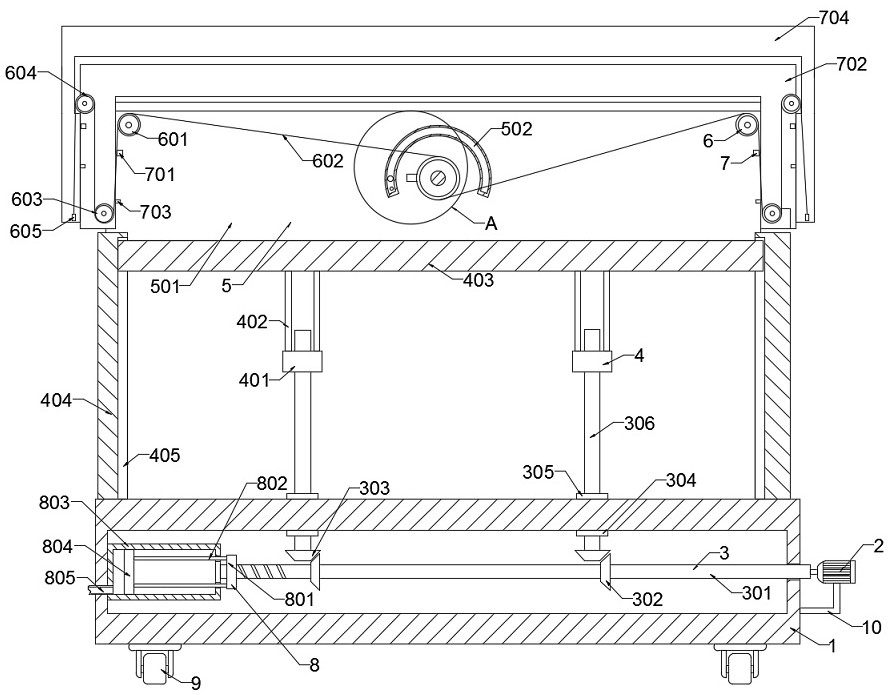
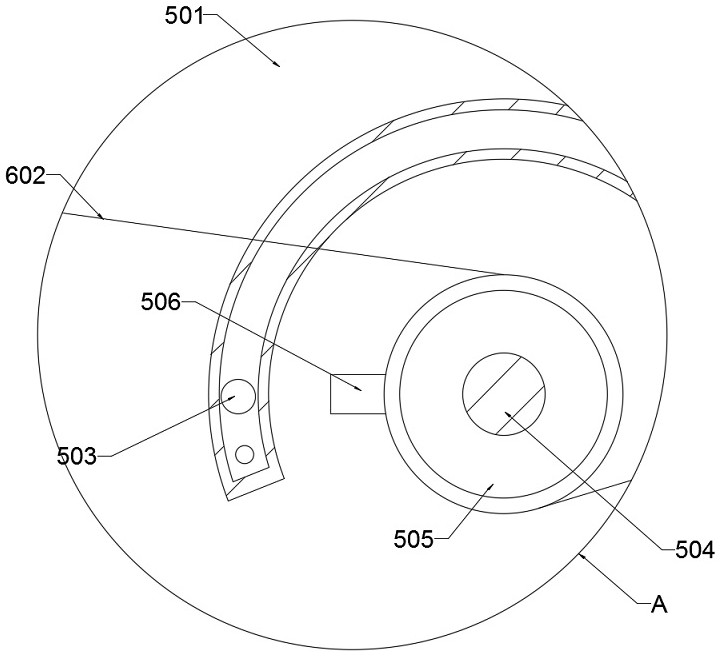
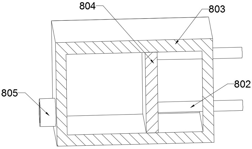
[0025] refer to Figure 1-5 , a lifting structure for building construction, including a base 1, a motor 2, a driving mechanism 3, a lifting mechanism 4, a pulling mechanism 5, a rotating mechanism 6, a placing mechanism 7, a hydraulic mechanism 8, a universal wheel 9 and a folding ro...


PUM


Abstract

The invention discloses a lifting structure for building construction. The lifting structure comprises a base, a motor, a driving mechanism, a lifting mechanism, a pulling mechanism, a rotating mechanism, a placing mechanism, a hydraulic mechanism, universal wheels and a folding rod, wherein the motor is welded and fixed on the side wall of the base through the folding rod, the bottom wall of the base is fixedly connected with a plurality of universal wheels, the top wall of the base is welded and fixed with the lifting mechanism, the top of the lifting mechanism is welded and fixed with the pulling mechanism, the inner wall of the base is welded and fixed with the hydraulic mechanism, and the output end of the motor is welded and fixed with the driving mechanism. According to the invention, the lifting mechanism is arranged, two first nuts synchronously move up and down on the side wall of a first lead screw, and the first nuts have a self-locking function, so that the two first nuts drive a plurality of first push rods and a bearing plate to slide in a sliding groove of a supporting plate together, lifting operation of the upper and lower positions is carried out on a building worker, the bearing plate can be lifted to any height in the stroke, the operation is simple and convenient, and the safety coefficient is high.

Description

technical field [0001] The invention relates to the technical field of building engineering, in particular to a lifting structure for building construction. Background technique [0002] Building construction refers to the production activities in the implementation stage of engineering construction. It is the construction process of various buildings. It can also be said to be the process of turning various lines on the design drawings into physical objects at designated locations. It includes basic engineering construction. , main structure construction, roofing engineering construction, decoration engineering construction, etc., the place where the construction work is called "building construction site" or "construction site", also called construction site. [0003] It is often necessary to use a lifting structure at the construction site to carry out construction on the surface of the building at different heights. The current lifting mechanism often uses a step ladder,...

Claims


Application Information

Patent Timeline
Patent Type & Authority Applications(China)
IPC IPC(8): E04G1/24E04G1/18E04G1/22E04G1/15
CPCE04G1/24E04G1/18E04G1/22E04G1/15E04G2001/242
Inventor 张晓红
Owner 湖南玖环建设工程有限公司
Learn More