Multifunctional fan

A multi-functional, fan technology, applied in space heating and ventilation, space heating and ventilation details, air heaters, etc., can solve problems such as fog is not ornamental, uneven air outlet, turbulent airflow, etc. , to achieve the effect of improving humidification effect, avoiding electric leakage, and various functions

Active Publication Date: 2021-10-15
CROP CIRCLE TECH CO LTD
View PDF9 Cites 0 Cited by
  • Summary
  • Abstract
  • Description
  • Claims
  • Application Information

AI Technical Summary

Problems solved by technology

[0002] The existing humidification fan, including the combination of the fan device and the humidification device, realizes the functions of humidification and air supply, the air flow is turbulent, and the wind is uneven. The user observes that the mist is sprayed out for humidification, and the mist is not ornamental. Therefore, it is very important to invent a fan with no turbulent airflow, even airflow and ornamental mist.

Method used


Image

  • Multifunctional fan
  • Multifunctional fan
  • Multifunctional fan

Examples


Embodiment

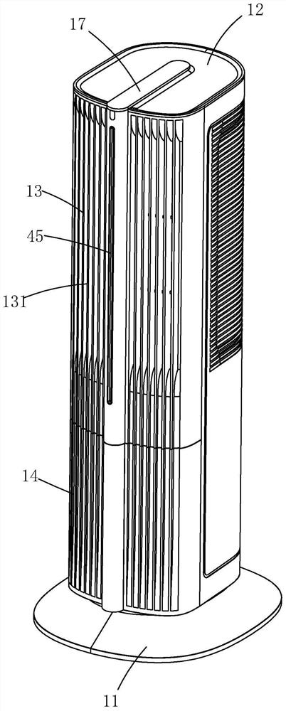
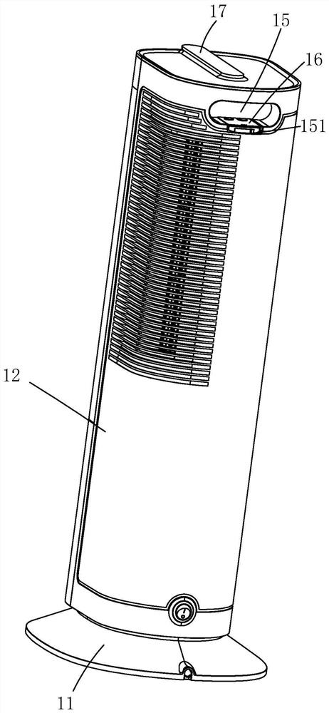
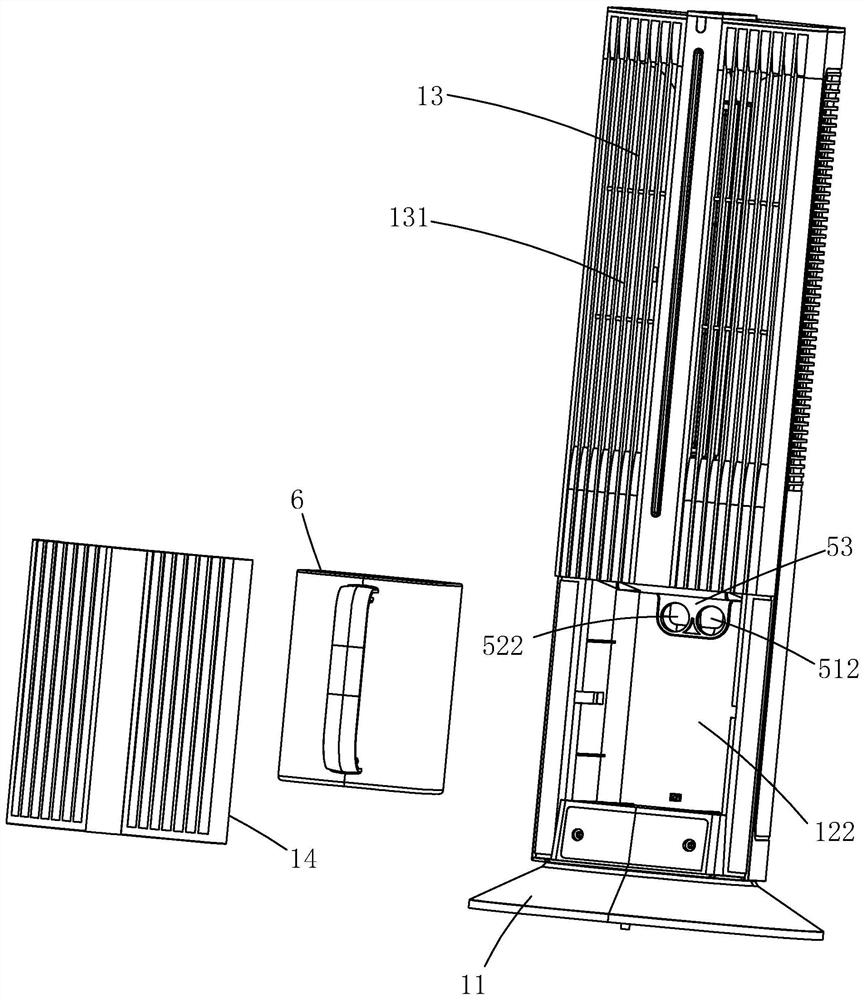
[0066] Example, combined with Figure 1 to Figure 44 As shown, a humidifying heater includes a casing, a water tank 6, an atomizing device 7, an energy gathering ring 300, a first air supply device 2, an air passage 3, a mist outlet pipeline 4, a dumping anti-leakage device, a second Air blower 400 , heating element 100 , energy gathering ring 300 , function control panel 17 and remote control 16 .

[0067] The casing 1 includes a base 11, a casing 12, an upper panel 13 and a lower panel 14, the casing 12 has an upper cavity 121 and a lower cavity 122, and the bottom of the lower cavity 122 is provided with a The conductive contact part 123, the upper panel 13 has a wind and mist outlet 131, the upper panel 13 is assembled with the housing 12, the upper panel 13 blocks the upper cavity 121, and the lower panel 14 is assembled with the housing 12 in a detachable manner, The lower panel 14 covers the lower cavity 122, and the back of the housing 12 is close to the top position ...

Embodiment 2

[0112] Embodiment 2, the difference between embodiment 2 and embodiment 1 is: the structure of the water tank 6 in embodiment 2 is changed, the energy gathering ring 300 is canceled, and the atomization device 7 adopts a suspension type atomization device 8 .

[0113] The side wall of the water tank 6 is provided with an air inlet 61 and a mist outlet 62. The side wall of the water tank 6 is provided with an air inlet connection pipe 63 and a mist outlet connection pipe 64. The air inlet connection pipe 63 is connected to the air inlet 61. The mist outlet connecting pipe 64 is connected to the mist outlet 62, the air inlet connecting pipe 63 and the mist outlet connecting pipe 64 are both sleeved with a sealing ring 65, and the other side wall of the water tank 6 is provided with a handle 66 , the top of the water tank 6 has a water injection port 67, and the water injection port 67 is provided with a top sealing cover 68, and the top sealing cover 68 is detachably fastened to ...

Embodiment 3

[0123] Embodiment 3, the difference between embodiment 3 and embodiment 1 is: the embodiment 3 cancels the dumping anti-leakage device, and the air outlet of the second air supply device 4 is directly connected to the air inlet connecting pipe 63 of the water tank 6, so The opening 42 of the mist outlet pipeline 4 is directly connected to the mist outlet connection pipe 64 of the water tank 6 .


PUM


Abstract

The invention relates to a multifunctional fan which comprises a machine shell, a water tank, an atomization device, a first air supply device, a second air supply device and a mist outlet pipeline. The machine shell is provided with an air mist outlet, the first air supply device is arranged in the machine shell, and an air outlet of the first air supply device communicates with the air mist outlet. The atomization device is arranged in the water tank, an air inlet and a mist outlet are formed in the water tank, the water tank is detachably arranged in the machine shell, the second air supply device is arranged in the machine shell, and an air outlet of the second air supply device communicates with the air inlet. One port of the mist outlet pipeline is closed to form a closed end, the other port of the mist outlet pipeline is opened to form an opening, a mist outlet gap is formed in the pipe wall of the mist outlet pipeline, the mist outlet pipeline is arranged in the machine shell, the opening communicates with the mist outlet, and the mist outlet gap communicates with the mist outlet. A user can switch the air supply function, the humidification function and the air supply humidification function at will, and different requirements of the user are met.

Description

technical field [0001] The invention relates to a multifunctional fan. Background technique [0002] The existing humidification fan, including the combination of the fan device and the humidification device, realizes the functions of humidification and air supply. The air flow is turbulent and the air is not uniform. Therefore it is very important to invent a kind of air-out airflow without turbulence, and the air-out is uniform, and the mist is equipped with ornamental fan. Contents of the invention [0003] The purpose of the present invention is to provide a multi-functional fan with no turbulence, uniform air output and humidification function. [0004] The purpose of the present invention is achieved like this: [0005] A multifunctional fan, comprising a casing, a water tank, an atomizing device, a first air supply device, a second air supply device and a mist outlet, the casing is provided with a wind mist outlet, and the first air supply device It is arranged i...

Claims


Application Information

Patent Timeline
Patent Type & Authority Applications(China)
IPC IPC(8): F24F6/12F24F11/65F24F13/00F24F13/08F24H3/02F24H9/18F04D25/08
CPCF24F6/12F24F11/65F24F13/00F24F13/08F24H3/022F24H9/1863F04D25/08Y02B30/54
Inventor 林栋联龙美双谢永圣李景进黄涛许国栋李鲁
Owner CROP CIRCLE TECH CO LTD
Why Eureka
Try Eureka