Eureka AIR delivers breakthrough ideas for toughest innovation challenges, trusted by R&D personnel around the world.

Vehicle seat device

A technology for seats and vehicles, which can be applied to vehicle seats, special positions of vehicles, vehicle components, etc., and can solve problems such as decreased texture

Inactive Publication Date: 2021-10-19
AISIN CORP
View PDF1 Cites 0 Cited by
  • Summary
  • Abstract
  • Description
  • Claims
  • Application Information

AI Technical Summary

Problems solved by technology

Then, its texture may be degraded thereby, so there is room for improvement in this proposal

Method used


Image

  • Vehicle seat device
  • Vehicle seat device
  • Vehicle seat device

Examples


Embodiment Construction

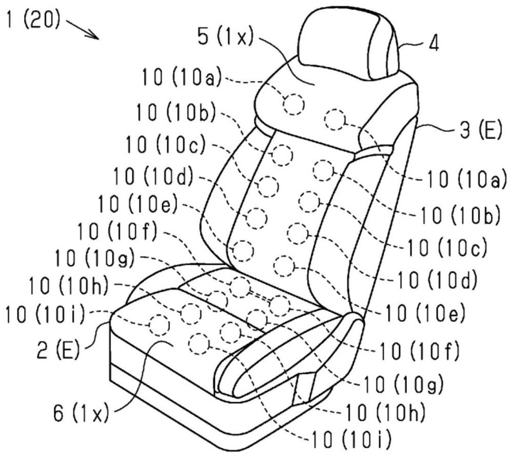
[0032] Such as figure 1 As shown, a vehicle seat 1 includes a seat cushion 2 and a seat back 3 provided at a rear end portion of the seat cushion 2 . Furthermore, a headrest 4 is provided on the upper end of the seat back 3 .

[0033] In addition, the seat 1 of the present embodiment is provided with a plurality of air pockets 10a to 10h that expand and contract inside the seat cushion 2 and the seat back 3 to press the seat skin 1x from the inside. Then, in the present embodiment, the seat device 20 capable of imparting a relaxation effect to the occupant seated on the seat 1 based on the pressing action of the air bladders 10 is formed.

[0034] In the seat 1 of the present embodiment, the air bags 10 a to 10 e for relaxation are provided along the backrest surface 5 inside the seat back 3 . Furthermore, the air bags 10f to 10i for relaxation are provided along the seating surface 6 of the seat cushion 2 in the same manner.

[0035] Specifically, the air bags 10 a to 10 e...


PUM


Abstract

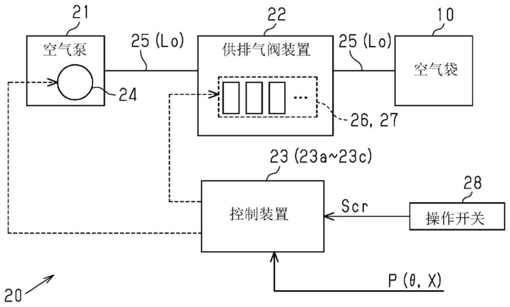
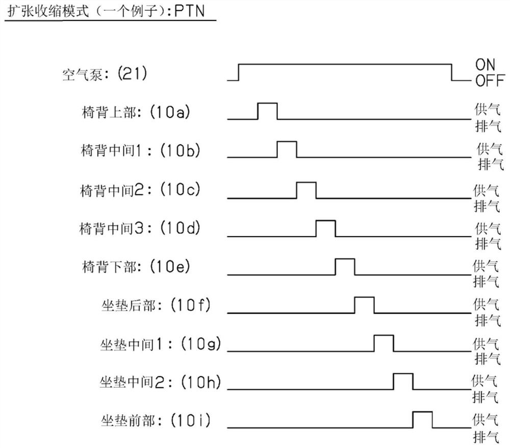
The invention provides a vehicle seat device which enables an air bag for relaxing to be expanded and contracted more suitably. A control device constituting a seat device (20) has a function as an expansion / contraction mode setting unit for setting an expansion / contraction mode of each of a plurality of air bags (10) which expand by supply of air and press a seat skin (1x) from the inside. In addition, the control device has a function as an adjustment position detection unit that detects the adjustment position of the seat element for the seat (1) provided with each air bag. In addition, the control device has a function as a pressing action reduction region estimation unit that estimates the presence of a pressing action reduction region in which the pressing action of the seat skin due to the expansion of the air bag is reduced, on the basis of the adjustment position of the seat element. The control device then sets an expansion / contraction mode in which the air bag located in the pressing action reduction region is excluded from among the air bags when it is estimated that the pressing action reduction region exists.

Description

technical field [0001] The present invention relates to a vehicle seat device. Background technique [0002] Conventionally, some seat devices for vehicles include an air bag provided inside a seat skin, and an air supply / exhaust device for expanding and contracting the air bag. For example, the seat device described in Patent Document 1 includes a plurality of air pockets that expand when filled with air to press the seat skin from the inside. And it is comprised so that the occupant seated in the seat may be given a relaxation effect by the pressing action of each of these air bags. [0003] In addition, in the seat device of this conventional example, when the headrest is located at the lower limit position, the supply of air to the air bag disposed at the upper end portion of the seat back is stopped. That is, when the passenger seated in the seat is short, the air bag arranged at the upper end portion of the seat back may be positioned above the shoulder of the passen...

Claims


Application Information

Patent Timeline
Patent Type & Authority Applications(China)
IPC IPC(8): B60N2/90B60N2/62B60N2/64
CPCB60N2/976B60N2/62B60N2/64B60N2/914B60N2/06B60N2/22B60N2/0272B60R21/231B60R2021/0002B60R21/207
Inventor 伊藤雄大藤井雄辉
Owner AISIN CORP
Why Eureka
Eureka Blog
Learn More