An energy-saving quick-connect device for construction equipment

A technology for construction equipment and mounting seats, which is applied in the direction of construction and building construction, can solve problems such as troublesome connection methods of connecting rods, environmental pollution on the construction site, and low connection efficiency, so as to save operating time, reduce energy consumption, and improve The effect of connection efficiency

Active Publication Date: 2022-03-15
乾日安全科技(北京)有限公司
9 Cites 0 Cited by

AI-Extracted Technical Summary

Problems solved by technology

[0002] The commonly used pouring method in construction engineering is concrete pouring on site, but this method not only takes up space but also pollutes the environment on the construction site. In order to solve the defects of the above pouring methods, prefabricated buildings have appeared. The components are poured in the factory in advance according to the standard, and th...

Method used

[0052] The above-mentioned quick-connecting device can be made of materials such as ABS, and the ABS material can be recycled for secondary...

Abstract

This application relates to the technical field of construction equipment components, in particular to an energy-saving quick-connect device for construction equipment, which includes a base, a mounting mechanism and a fixing mechanism. The mounting mechanisms are respectively provided with a set on opposite sides of the base, The mounting mechanism includes a first mounting plate and a second mounting plate, the first mounting plate and the second mounting plate are spaced and vertically fixed on the base, the fixing mechanism includes an adjusting rod and a push plate, and the adjusting The rod is passed through the first mounting plate and is threadedly connected with the first mounting plate, and the push plate is located between the first mounting plate and the second mounting plate and is rotatably connected with the adjusting rod. The present application has the effect of improving the connection efficiency of prefabricated components.

Application Domain

Technology Topic

Image

  • An energy-saving quick-connect device for construction equipment
  • An energy-saving quick-connect device for construction equipment
  • An energy-saving quick-connect device for construction equipment

Examples

  • Experimental program(3)

Example Embodiment

[0037] Example 1
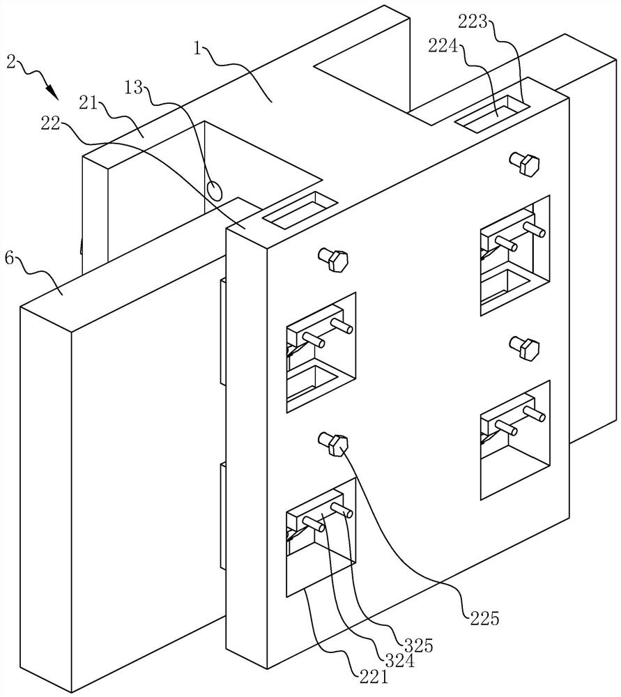
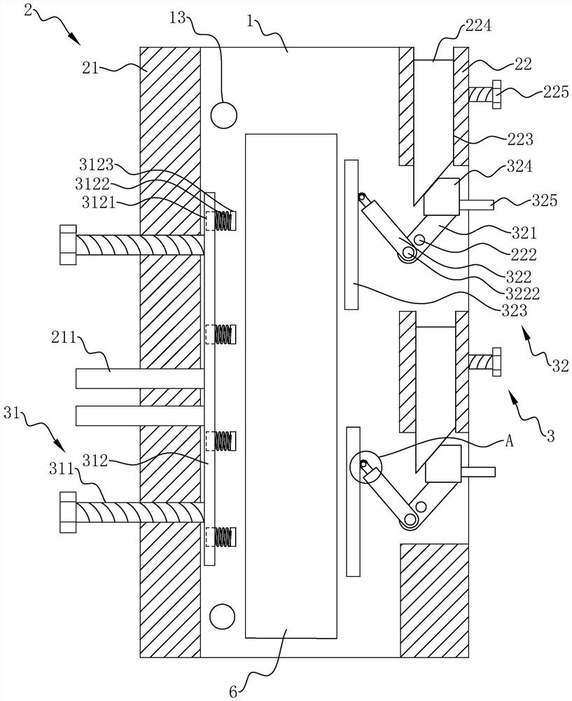
[0038] The embodiment of the present application discloses an energy-saving quick-connect device for construction equipment, refer to figure 1 and figure 2 , which includes a base 1 , an installation mechanism 2 and a fixing mechanism 3 .
[0039] refer to figure 1 , the base 1 is a cubic structure, which is used for the installation and connection of the installation mechanism 2 here.
[0040] refer to figure 1 and figure 2 , the installation mechanism 2 includes a first installation plate 21 and a second installation plate 22, which are used for the installation of the fixing mechanism 3 here. The first mounting plate 21 and the second mounting plate 22 are vertically fixed on the base 1 at intervals.
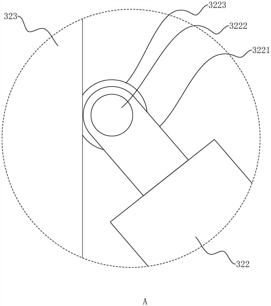
[0041] refer to figure 2 , the fixing mechanism 3 includes an adjusting piece 31 arranged on the first mounting plate 21 and a clamping piece 32 arranged on the second mounting plate 22, the adjusting piece 31 includes an adjusting rod 311 and a push plate 312, and the adjusting rod 311 is a threaded rod , which is vertically penetrated on the first mounting plate 21 and is threadedly connected with the first mounting plate 21 , both ends of the adjusting rod 311 penetrate the first mounting plate 21 , and the push plate 312 is located between the first mounting plate 21 and the second mounting plate 21 22 and perpendicular to the base 1 , one end of the adjusting rod 311 is rotatably connected to the push plate 312 through a bearing, and the push plate 312 can be controlled to move toward or away from the first mounting plate 21 by twisting the adjusting rod 311 .
[0042] In order to make the movement of the push plate 312 more stable and smooth, two guide rods 211 can be spaced and vertically penetrated on the first installation plate 21, and each guide rod 211 is slidably connected to the first installation plate 21 and has one end connected to the push rod 211. The plate 312 is fixedly connected, and when the push plate 312 moves, the guide rod 211 can play a guiding role, so that the movement of the push plate 312 is more stable and smooth.
[0043] refer to figure 2 and image 3, the clamping member 32 is used here to cooperate with the adjusting member 31 to realize the clamping and fixing of the prefabricated member 6, which includes a clamping plate 321, a connecting plate 322 and a top plate 323, and an installation opening 221 is opened on the second installation plate 22, A rotating shaft 222 perpendicular to the base 1 is fixed in the installation port 221. A through hole is formed on the clamping plate 321. The clamping plate 321 is sleeved on the rotating shaft 222 through the through hole and can be rotated on the rotating shaft 222. Two mounting ears 3221 are fixed axially at both ends, and a hinge shaft 3222 is arranged between two adjacent mounting ears 3221. One end is also provided with a through hole through which the clamping plate 321 is sleeved on one of the hinge shafts 3222 of the connecting plate 322 to realize the rotational connection between the clamping plate 321 and the connecting plate 322. A sleeve 3223 is sleeved on the hinge shaft 3222 , and the top plate 323 is fixed on the sleeve 3223 to realize the rotational connection between the top plate 323 and the connecting plate 322 .
[0044] refer to figure 2 One end of the second mounting plate 22 is provided with a socket 223 that communicates with the mounting port 221, a top block 224 is inserted in the socket 223, and a top rod 225 is pierced through the outer wall of the second mounting plate 22 near the socket 223. The top rod 225 It is a threaded rod, which is threadedly connected with the second mounting plate 22 , and the top rod 225 is screwed so that the top rod 225 penetrates into the socket 223 , so that the top block 224 is firmly fixed in the socket 223 .
[0045] When in use, place the two prefabricated components 6 to be connected on the two sets of installation mechanisms 2 respectively, and make the two prefabricated components 6 between the push plate 312 and the top plate 323, and then firstly rotate the adjusting rod 311 to push the push plate 311. The plate 312 is attached to the prefabricated member 6 , and then the connecting plate 322 is rotated to attach the top plate 323 to the prefabricated member 6 , and the top block 224 in the socket 223 is pushed into the installation opening 221 until the top block 224 and the clamping plate 321 abut At this time, the clamping plate 321 can be limited by pressing and fixing the top block 224 with the top rod 225 , so that the prefabricated member 6 is clamped and fixed between the push plate 312 and the top plate 323 .
[0046] refer to figure 2 In order to improve the fixing effect, two adjustment rods 311 can be provided on the first mounting plate 21 , and two sets of clamping members 32 can be provided on the second mounting plate 22 .
[0047] In order to facilitate the fine-tuning of the position of the clamped and fixed prefabricated member 6, it can be further configured that: the side of the push plate 312 facing away from the adjustment rod 311 is evenly provided with four countersunk holes 3121, and each countersunk hole 3121 has four countersunk holes 3121. A spring 3122 is fixed coaxially, and each spring 3122 exposes a countersunk hole 3121 in a state of no force, and a washer 3123 is coaxially fixed to the end of each spring 3122 away from the countersunk hole 3121 for fine adjustment. At this time, the adjusting rod 311 can be rotated first to make the washer 3123 abut on the prefabricated member 6, and then the control card 321 can drive the top plate 323 to push the prefabricated member 6 by linking the connecting plate 322. At this time, the prefabricated member 6 will squeeze the spring 3122, After the fine adjustment of the position of the prefabricated member 6 is completed, the top block 224 is used to clamp the fixed card plate 321, and then the adjusting rod 311 is rotated until the push plate 312 is in contact with the prefabricated member 6. At this time, the spring 3122 will be completely located in the countersunk head. inside the hole 3121.
[0048] The above-mentioned setting of the spring 3122 can realize the pre-positioning of the prefabricated member 6 before clamping and fixing, and realize the fine adjustment of the position of the prefabricated member 6 according to the retractable characteristics of the spring 3122. The elastic force of the spring 3122 due to being compressed can make the clamping effect of the push plate 312 and the top plate 323 better.
[0049] refer to figure 2 , in order to improve the clamping strength between the top block 224 and the clamping plate 321, a transition block 324 can be fixed at the end of the clamping plate 321 away from the connecting plate 322. When the top block 224 is clamped with the clamping plate 321, it will It is in direct contact with the transition block 324, and the positions where the top block 224 and the transition block 324 contact each other are machined with inclined surfaces, and the two inclined surfaces can be completely fitted during clamping to increase the contact area between the top block 224 and the transition block 324, thereby increasing the contact area between the top block 224 and the transition block 324. The clamping strength between the top block 224 and the clamping plate 321 is improved.
[0050] In order to facilitate the rotation of the clamping plate 321 , two pressing rods 325 may be fixedly connected to the transition block 324 at intervals.
[0051] refer to figure 2 , in order to facilitate the pipeline routing for construction, buried wire holes 13 can be opened on the base 1, the buried wire holes 13 radially penetrate the base 1, and the number of buried wire holes 13 can be opened according to the actual application.
[0052] The above-mentioned quick-connecting device can be made of materials such as ABS, and the ABS material can be recycled and reused, so it is more energy-saving and environmentally friendly, which is beneficial to the wide popularization and application of the quick-connecting device.
[0053] The implementation principle of an energy-saving quick-connect device for construction equipment in the embodiment of the present application is as follows: when in use, connect the two prefabricated components 6 to be connected between the first mounting plate 21 and the second mounting plate 22 on both sides of the base 1 respectively. , and then clamp and fix it by the fixing mechanism 3 .
[0054] With this embodiment, the quick connection device can realize the quick connection of the prefabricated components 6 , thereby improving the connection efficiency of the prefabricated components 6 , saving operation time, and reducing the consumption of energy such as material and manpower.

Example Embodiment

[0055] Embodiment 2
[0056] The difference between this embodiment and the first embodiment is that the quick connection device in this embodiment can change the installation angle of the two prefabricated components 6 in a coplanar state. Divided into two parts, the two divided parts are called the first mounting seat 11 and the second mounting seat 12 respectively, and two hinges 4 are arranged at the adjacent ends of the two mounting seats. The sheets are respectively fixed to the side of the two mounting seats away from the mounting mechanism 2, and the first mounting seat 11 and the second mounting seat 12 can be turned over through the hinge 4, thereby changing the two prefabricated components 6 in a coplanar state. The installation angle increases the diversity when the prefabricated components 6 are connected and installed.

Example Embodiment

[0057] Embodiment 3
[0058] The difference between this embodiment and the first embodiment is that the quick-connect device in this embodiment can change the installation angle of the two prefabricated components 6 in a non-coplanar state, specifically: Similarly, the base 1 in this embodiment is also It is divided into two parts along the symmetry line of the two sets of installation mechanisms 2, and the divided two parts are also called the first installation seat 11 and the second installation seat 12 respectively. Position slot 111, the position slot 111 is perpendicular to the installation mechanism 2 and runs through the first mounting seat 11, and a hinge rod 112 is arranged in the center of the position slot 111 parallel to the first mounting seat 11, and the two ends of the hinge rod 112 are respectively inserted The groove walls on both sides of the abdication groove 111 are connected in rotation with the groove walls opposite to the abdication groove 111. A rotating rod 5 is fixed on the hinge rod 112. The rotating rod 5 is a threaded rod, and the rotating rod 5 is along the diameter of the hinge rod 112. The rotating rod 5 can just be inserted into the giving way slot 111 and the length of the rotating rod 5 is slightly larger than half the length of the giving way slot 111 .
[0059] The side of the second mounting seat 12 facing away from the mounting mechanism 2 is fixed with a threaded sleeve 121 , and the threaded sleeve 121 is threadedly connected with the rotating rod 5 , and the second mounting seat 12 is also provided with a passing hole 122 communicating with the threaded sleeve 121 . .
[0060] In use, the second mounting seat 12 is rotated to realize the angle adjustment between the second mounting seat 12 and the first mounting seat 11 in the circumferential direction through the threaded sleeve 121. A distance between the mounting seat 11 and the second mounting seat 12 can be adjusted by rotating the rotating rod 5 in the radial direction between the second mounting seat 12 and the first mounting seat 11 .
[0061] The above structure can further increase the diversity of the connection and installation of the prefabricated components 6 , and add more possibilities for the connection of the prefabricated components 6 .

PUM

no PUM

Description & Claims & Application Information

We can also present the details of the Description, Claims and Application information to help users get a comprehensive understanding of the technical details of the patent, such as background art, summary of invention, brief description of drawings, description of embodiments, and other original content. On the other hand, users can also determine the specific scope of protection of the technology through the list of claims; as well as understand the changes in the life cycle of the technology with the presentation of the patent timeline. Login to view more.

Similar technology patents

Classification and recommendation of technical efficacy words

  • Shorten working time
  • Improve connection efficiency
Why Eureka
Try Eureka