
Side light-emitting system of thin lamp box

A side lighting and light box technology, applied in the field of side lighting systems, can solve the problem of dust and impurities affecting the lighting effect of thin light boxes, and achieve the effect of easy adjustment and good light display effect.

Active Publication Date: 2021-10-19
MYNICE OPTOELECTRONICS CO LTD
View PDF11 Cites 0 Cited by
  • Summary
  • Abstract
  • Description
  • Claims
  • Application Information

AI Technical Summary

Problems solved by technology

[0004] In view of the above-mentioned related technologies, the inventor believes that the heat dissipation holes are always open, and some dust and impurities can easily enter the interior of the fixed frame, thereby affecting the luminous effect of the thin light box

Method used


Image

  • Side light-emitting system of thin lamp box
  • Side light-emitting system of thin lamp box
  • Side light-emitting system of thin lamp box

Examples


Embodiment 1

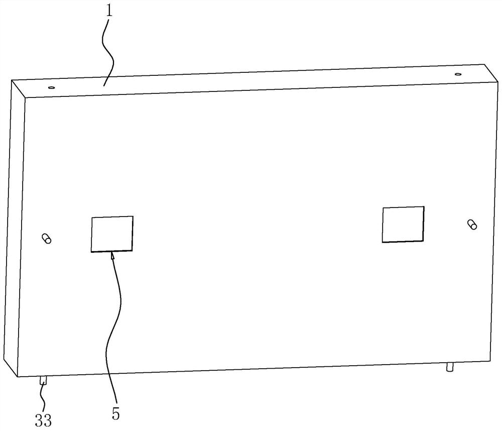
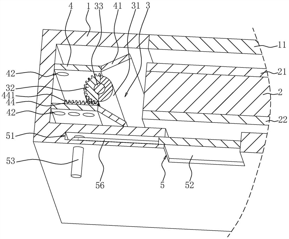
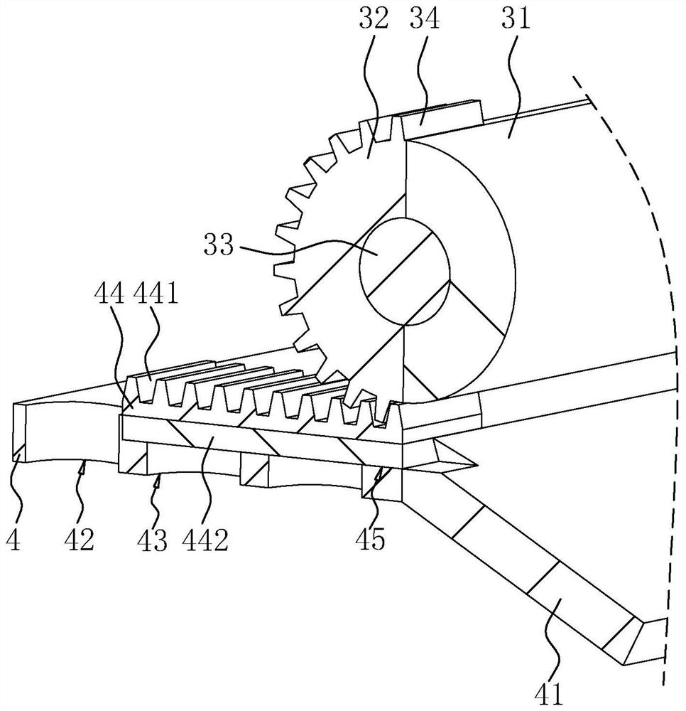
[0035] The embodiment of the present application discloses a side lighting system of a thin light box. refer to figure 1 and figure 2 , the side lighting system includes a frame 1 of hollow structure, and a panel 11 is installed on one side wall of the frame 1 . A light guide plate 2 is arranged inside the frame 1 , an album layer 21 for display is fixedly connected between the light guide plate 2 and the panel 11 , and a reflective film 22 is fixedly connected to the side of the light guide plate 2 away from the album layer 21 . Two light sources 3 are arranged inside the frame 1 , and the two light sources 3 are respectively located on both sides of the light guide plate 2 .

[0036] The heights of the light guide plate 2, album layer 21, and reflective film 22 are the same as those inside the frame 1, the light source 3 is cylindrical, and the height of the light source 3 is equal to the height of the light guide plate 2, and the light source 3 is vertical. Vertical ori...

Embodiment 2

[0051] The embodiment of the present application discloses a side lighting system of a thin light box. refer to Figure 5 , the difference from the first embodiment is that two light sources 3 are arranged between every two baffles 4 . When it is necessary to control the luminous intensity of the thin light box to become weaker, control the two light sources 3 to rotate in opposite directions. The two light sources 3 rotate in opposite directions so that the two light sources 3 are relatively centered to reduce the light irradiated on the light guide plate 2, which is convenient for the thin light box. More uniform light emission.


PUM


Abstract

The invention relates to the field of thin lamp boxes, in particular to a side light-emitting system of a thin lamp box, which comprises a frame with a hollow structure, a light guide plate is arranged in the frame, a vent hole is formed in one side wall of the frame, a bearing groove is formed in one side wall of the vent hole, and a bearing plate with one end extending into the vent hole is slidably connected in the bearing groove. A driving shaft is arranged in the bearing groove, the two ends of the driving shaft penetrate through the side wall, provided with the vent holes, of the frame, a circular clamping groove is formed in the inner side wall, provided with the vent holes, of the frame, a circular elastic block clamped with the clamping groove is fixed to the end, located in the frame, of the driving shaft, and a driving rope is wound around the side wall, located in the bearing groove, of the driving shaft. The end of the driving rope near the bearing plate is fixedly connected with the bearing plate. A spring is fixed between the bearing plate and the side wall, away from the driving shaft, of the vent hole, and the elasticity of the spring is larger than the friction force of clamping of the elastic block and the clamping groove. The side light-emitting system has the effect of reducing the situation that dust and impurities affect the light-emitting effect of the thin lamp box.

Description

technical field [0001] The present application relates to the field of thin light boxes, in particular to a side lighting system for thin light boxes. Background technique [0002] With the continuous development of all walks of life, lamps have been applied to many fields, such as advertising signs, signboards, window advertisements, mural screens, suspended ceilings, road signs, and console dashboards that need to be displayed at night. And along with more and more extensive use of lamps and lanterns, people's requirement to lamps and lanterns is also constantly improving, and more and more lamps and lanterns with advantages such as energy saving, attractive in appearance, light and handy emerge. [0003] The existing Chinese patent with publication number CN107993590A discloses a side light source ultra-thin light box system, which includes a light guide plate and a panel, the light guide plate and the panel are combined through a fixed frame, the light guide plate is fix...

Claims


Application Information

Patent Timeline
IPC IPC(8): G09F13/04
CPCG09F13/0413G09F13/0409
Inventor 王华陈林
Owner MYNICE OPTOELECTRONICS CO LTD
Learn More