
Distributed energy emission regeneration device

A technology of distributed energy and regenerative devices, applied in separation methods, cleaning hollow objects, dispersing particle filtration, etc., can solve the problems of environmental pollution, waste, etc., and achieve the effects of easy conversion and utilization, easy cleaning, and smooth air intake

Pending Publication Date: 2021-10-22
卡奥斯能源科技有限公司
View PDF9 Cites 0 Cited by
  • Summary
  • Abstract
  • Description
  • Claims
  • Application Information

AI Technical Summary

Problems solved by technology

The primary energy is mainly gaseous fuel, supplemented by renewable energy, and all available resources are used; the secondary energy is mainly distributed in the heat, electricity, and cooling (value) cogeneration at the user end. An important application of distributed energy is the thermoelectricity of generating units. Combined power supply or combined cooling, heating and power supply, gas generator sets are generally commonly used units and are widely used, but high-temperature gas will be discharged during the working process of gas generator sets, which not only pollutes the environment, but also causes waste

Method used


Image

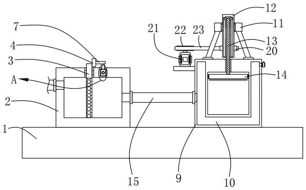
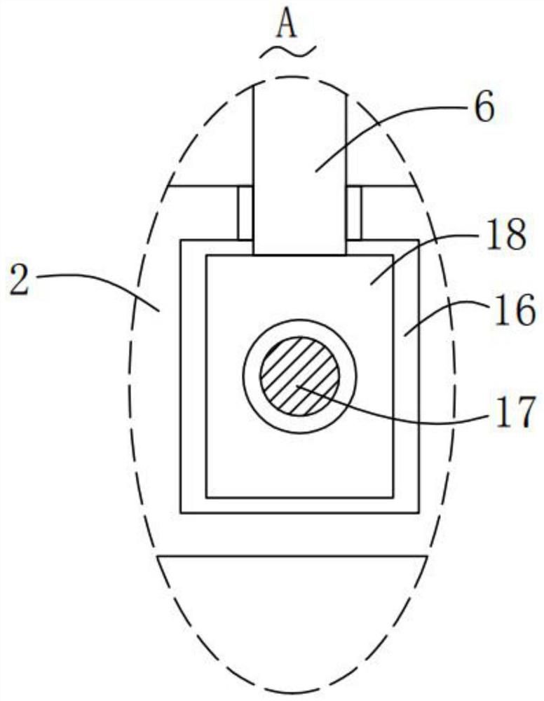
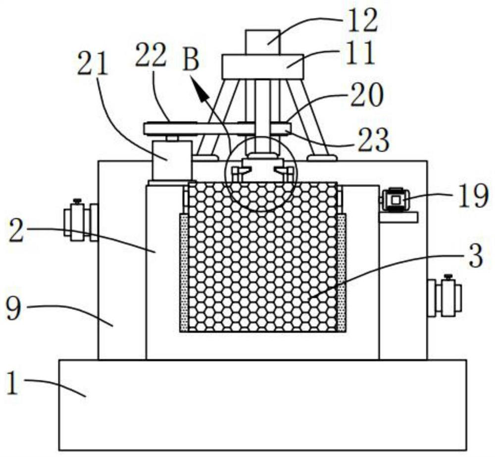
  • Distributed energy emission regeneration device
  • Distributed energy emission regeneration device
  • Distributed energy emission regeneration device

Examples


Embodiment

[0024] Please refer to Figure 1-5 The distributed energy emission regeneration device includes: a base 1; a filter box 2, which is fixedly installed on the top of the base 1; a filter screen 3, which is sealed and movable on the filter screen Inside the box 2, and the top of the filter screen 3 extends to the outside of the filter box 2; a fixed block 4, the fixed block 4 is fixedly installed on the filter screen 3; two card slots 5, two of the card slots 5 is set symmetrically on the fixed block 4; two support rods 6 are symmetrically slidably installed on the filter box 2; a connecting block 7 is fixedly installed on the The top of the support rod 6; the block 8, the block 8 is fixedly installed on the connecting block 7, and the block 8 is movably connected with the inner wall of the corresponding slot 5; the heating box 9, the The heating box 9 is fixedly installed on the top of the base 1; the cavity 10, the cavity 10 is opened on the heating box 9, and the cavity 10 co...


PUM


Abstract

The invention provides a distributed energy emission regeneration device. The distributed energy emission regeneration device comprises a base; a filter box fixedly mounted at the top of the base; a filter screen movably mounted in the filter box in a sealed manner, wherein the top of the filter screen extends out of the filter box; a fixed block fixedly mounted on the filter screen; two clamping grooves symmetrically formed in the fixing block; two supporting rods symmetrically mounted on the filter box in a sliding manner; a connecting block fixedly mounted at the top end of the supporting rod; and clamping blocks fixedly installed on the connecting blocks, wherein the clamping blocks are movably connected with the inner walls of the corresponding clamping grooves. The distributed energy emission regeneration device provided by the invention has the advantages that the use is convenient, the emission can be converted and regenerated, the environment is protected, and meanwhile, the waste is avoided.

Description

technical field [0001] The invention relates to the field of distributed energy technology, in particular to a distributed energy emission regeneration device. Background technique [0002] The so-called "distributed energy" refers to a comprehensive energy utilization system distributed at the user end. The primary energy is mainly gas fuel, supplemented by renewable energy, and all available resources are used; the secondary energy is distributed at the user end. Combined production is the main application. An important application of distributed energy is the combined heat and power supply of generator sets or the combined supply of cooling, heating and power. Gas-fired generator sets are generally commonly used units and are widely used, but high-temperature gas will be discharged during the working process of gas-fired generator sets. , not only pollute the environment, but also cause waste. [0003] Therefore, it is necessary to provide a distributed energy emission r...

Claims


Application Information

Patent Timeline
Patent Type & Authority Applications(China)
IPC IPC(8): B01D46/10B01D46/42B08B9/087F28C3/06
CPCB01D46/10B01D46/42B08B9/087F28C3/06
Inventor 邵凯柴纪强朱亮
Owner 卡奥斯能源科技有限公司
Learn More