Mechanical cultivator ground wheel drive power clutch mechanism

A ground wheel drive, clutch mechanism technology, applied in non-mechanical drive clutches, fluid drive clutches, agricultural machinery and implements, etc., can solve the problems of low operation efficiency, high labor intensity, complicated and cumbersome operations, etc. Low-intensity, easy-to-use effects

Pending Publication Date: 2017-05-31
SUNWU COUNTY NONGFA AGRI MACHINERY
View PDF10 Cites 0 Cited by
  • Summary
  • Abstract
  • Description
  • Claims
  • Application Information

AI Technical Summary

Problems solved by technology

[0002] In order to expand the operation adaptability of mechanical intertillage and weeding operation tools, ensure and improve the intertillage and weeding operation effect on different crops and under different natural conditions, a kind of intertillage and weeding teeth can be driven by the weeder with its own ground wheel and the external power of the tractor. The mechanical cultivator and weeder with roller rotation has been successfully developed by the applicant of this patent, and has been industrialized, and has been applied in production operations, and has achieved good technical results. However, it has been found in production practice that when the two driving forces interact When switching, it is necessary to disassemble or install the transmission chain or transmission sprocket and other components in the ground wheel power transmission system of the implement to complete the cutting or connection of the driving power of the ground wheel. The operation is complicated and cumbersome, the work efficiency is low, and the labor intensity is high.

Method used


Image

  • Mechanical cultivator ground wheel drive power clutch mechanism
  • Mechanical cultivator ground wheel drive power clutch mechanism

Examples


Embodiment Construction

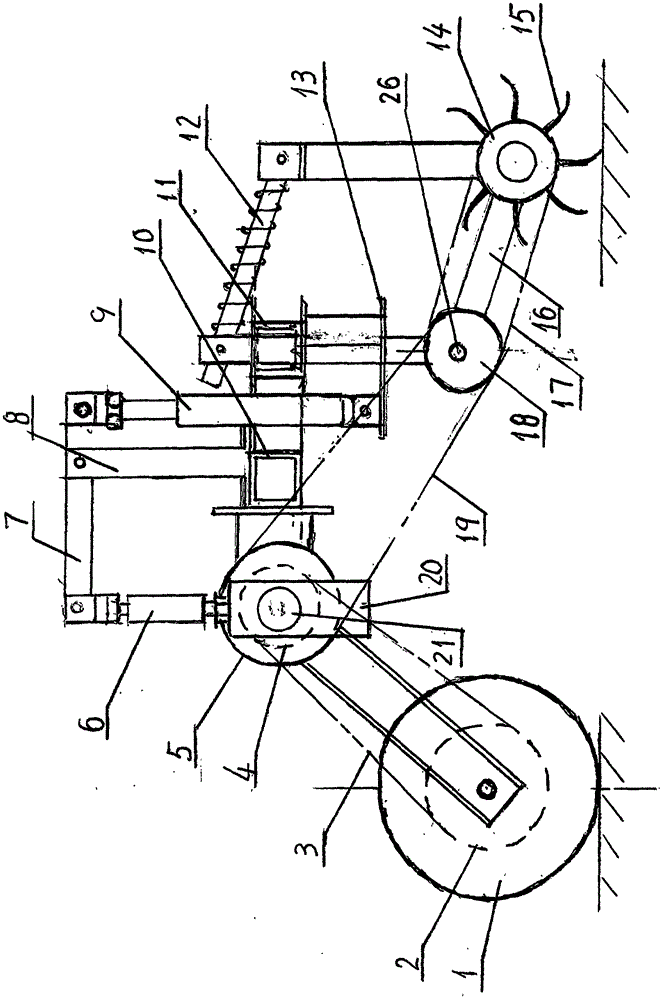
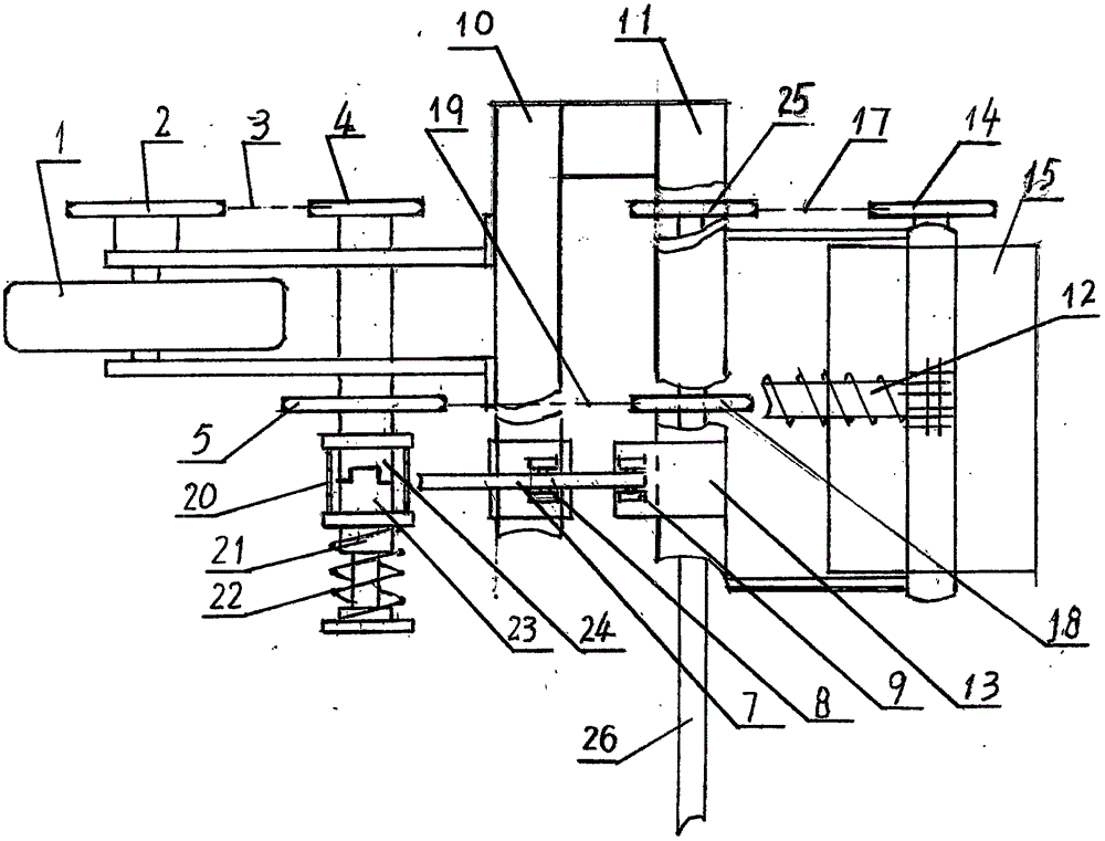
[0010] Embodiments of the present invention will be described in detail below in conjunction with the accompanying drawings. A ground wheel drive power clutch mechanism for a mechanical cultivator and weeder, equipped with a drive ground wheel 1 with a first sprocket 2 and a first drive shaft 21 with a second sprocket 4 on the frame front beam 10, The first chain 3 is sleeved on the first sprocket 2 and the second sprocket 4, and the second drive shaft 26, the fourth sprocket 18 and the fifth sprocket 25 are rotatably installed on the lower side of the frame rear beam 11 Fixedly mounted on the second drive shaft 26, on the rear side of the frame rear beam 11, the cultivating and weeding gear roller 15 with the sixth sprocket 14 is hingedly installed through the profiling telescopic rod 12, and the connecting support plate 16 The two ends are hingedly connected with the second drive shaft 26 and the cultivating and weeding gear roller 15 respectively, and the third chain 17 is ...


PUM


Abstract

The invention discloses a mechanical cultivator ground wheel drive power clutch mechanism, and belongs to agricultural machinery. A pressure spring, driving interlocking teeth, follow-up interlocking teeth and a third sprocket sequentially sleeve a first driving shaft, the third sprocket and the follow-up interlocking teeth are integrated, the driving interlocking teeth are radially and circumferentially positioned and assembled in an axially movable manner on the first driving shaft, the follow-up interlocking teeth, the third sprocket and the first driving shaft are axially and radially positioned and circumferentially matched in a rotatable manner, the third sprocket is welded with a cultivating and weeding tooth roller sequentially through a second chain, a fourth sprocket, a second driving shaft, a fifth sprocket, a third chain and a sixth sprocket, a driving and driven interlocking teeth separating mechanism comprises a bar frame, a swing bar, a bidirectional hydraulic cylinder, a fork holder and a cone plate separating fork, and the cone plate separating fork is inserted among the driving interlocking teeth and the follow-up interlocking teeth in a matched manner. Implement ground wheel power is conveniently and rapidly transferred, communicated or cut off, and the mechanical cultivator ground wheel drive power clutch mechanism has the advantages of novel and reasonable structure, reliability in use and low operation labor intensity.

Description

technical field [0001] The invention belongs to agricultural machinery, and mainly relates to a mechanical intertillage and weeding implement that can be driven by ground wheels and external power from a tractor. Background technique [0002] In order to expand the operation adaptability of mechanical intertillage and weeding operation tools, ensure and improve the intertillage and weeding operation effect on different crops and under different natural conditions, a kind of intertillage and weeding teeth can be driven by the weeder with its own ground wheel and the external power of the tractor. The mechanical cultivator and weeder with roller rotation has been successfully developed by the applicant of this patent, and has been industrialized, and has been applied in production operations, and has achieved good technical results. However, it has been found in production practice that when the two driving forces interact When switching, it is necessary to disassemble or inst...

Claims


Application Information

Patent Timeline
Patent Type & Authority Applications(China)
IPC IPC(8): A01B39/18A01B39/20F16D25/08
CPCA01B39/18A01B39/20F16D25/088
Inventor 张修春周长发张铁彬张德顺付文刚
Owner SUNWU COUNTY NONGFA AGRI MACHINERY
Why Eureka
Try Eureka