Guide profile and conveyor system

A technology for conveying systems and profiles, applied in the field of conveying systems, can solve problems such as troublesome replacement of sliding slats, and achieve the effect of simplifying installation and disassembly

Pending Publication Date: 2021-10-22
ROBERT BOSCH GMBH
View PDF1 Cites 0 Cited by
  • Summary
  • Abstract
  • Description
  • Claims
  • Application Information

AI Technical Summary

Problems solved by technology

[0003] The solution known from the prior art has the disadvantage that the sliding strips can only be pushed into the profile body on the end side
That is to say, it is very troublesome to replace the sliding slats at the conveyor system that has been manufactured, assembled and in operation, because the sliding slats to be replaced must also be removed from the profile on the end side. body pulled out

Method used


Image

  • Guide profile and conveyor system
  • Guide profile and conveyor system
  • Guide profile and conveyor system

Examples


Embodiment Construction

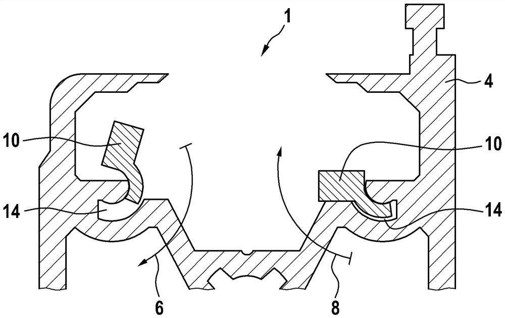
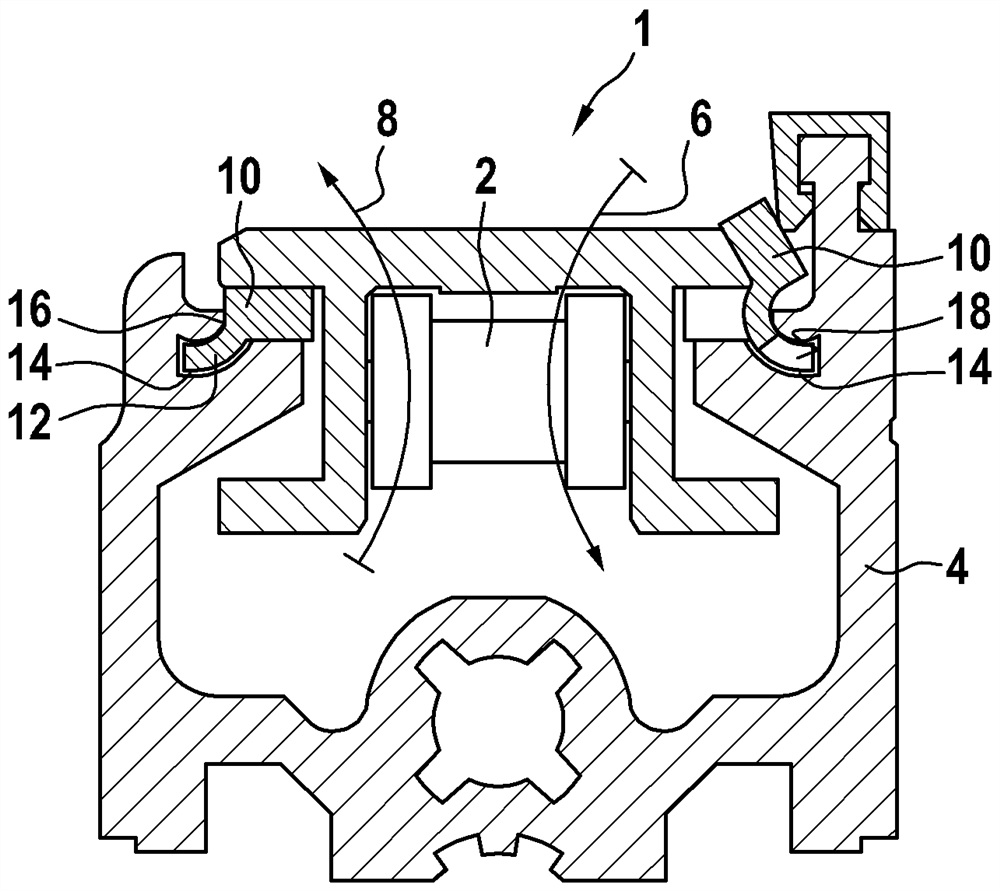
[0050] exist figure 1 shows part of a conveyor system 1 with a flat chain 2 , which is guided by means of a profile body 4 . The conveying direction of the conveying system 1 runs perpendicularly to the plane of the illustration in the present exemplary embodiment. The flat chain 2 is guided in a manner known per se along a sliding strip 10 which is held exchangeably on the profile body 4 . In order to illustrate the insertion and removal directions 6 , 8 of the sliding strips 10 , the right-hand sliding strip 10 is shown in the inserted position in the illustration. “Installation position” means the first installation step in which the sliding strip 10 is placed with the end section of a joint leg 12 on the recess 14 . The sliding slats 10 in their final position are shown on both sides.

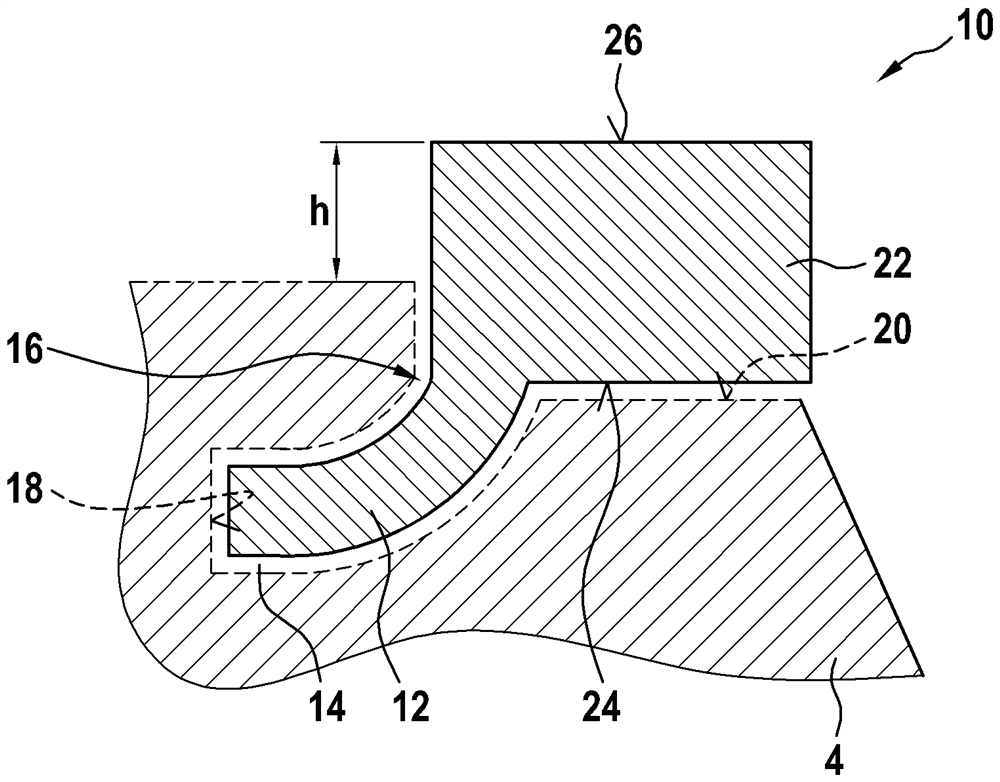
[0051] The sliding strip 10 is equipped with a curved joint leg 12 at the corner area 16 , which sinks into the recess 14 of the profile body 4 until the end part of the joint leg 12 abu...


PUM


Abstract

The present invention discloses guide profile and a conveying system. The conveying system is designed with a guide profile of this type. A slide bar of the guide profile is provided with an articulated leg so that it is possible to change the slide bar on the already installed conveying system.

Description

technical field [0001] The invention relates to a guide profile for a conveyor system according to claim 1 and a conveyor system according to claim 8 with such a guide profile. Background technique [0002] From the prior art, for example from DE 10 2005 046 302 A2, conveyor systems are known, also known as transfer systems, whose basic structure consists of a profile body in or at which a chain is guided . The chain may be a known flat chain or a fenced roller chain. In order to guide the chain better along the profile body, a sliding bar is provided, which is inserted, for example, into a recess in the profile body and at or on the sliding bar The above guides the chain. In this case, the chain is spaced from the profile body by the sliding strips, so that there is no direct contact between the chain and the profile body. The sliding strips are held in the recesses of the profile body by means of spring collets (Klipsen). [0003] A disadvantage of the solutions known...

Claims


Application Information

Patent Timeline
Patent Type & Authority Applications(China)
IPC IPC(8): B65G17/30B65G47/74
CPCB65G17/30B65G47/74B65G21/22B65G2207/48B65G15/62
Inventor H-P·布托M·基贝尔
Owner ROBERT BOSCH GMBH
Why Eureka
Try Eureka