Welding-free net rack node reinforcing structure

A structure strengthening and welding-free technology, which is applied in special structures, building components, building structures, etc., can solve problems such as the difficulty in reinforcement of bolt ball joints, and achieve the effects of increasing rigidity, ensuring safety, and facilitating construction

Pending Publication Date: 2021-10-22
CHINA CONSTR SENVENTH ENG BUREAU INSTALLATION ENG
View PDF14 Cites 2 Cited by
  • Summary
  • Abstract
  • Description
  • Claims
  • Application Information

AI Technical Summary

Problems solved by technology

[0004] In view of this, the purpose of the present invention is to provide a welding-free network frame node reinforcement structure to solve the technical problem of difficult reinforcement at the bolt ball node in the prior art

Method used


Image

  • Welding-free net rack node reinforcing structure
  • Welding-free net rack node reinforcing structure
  • Welding-free net rack node reinforcing structure

Examples


Embodiment 1

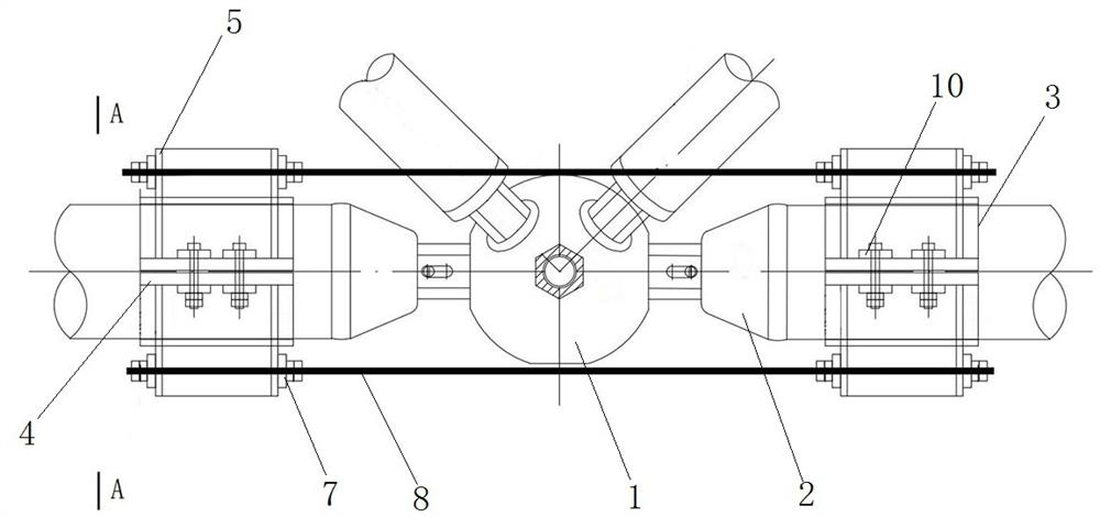
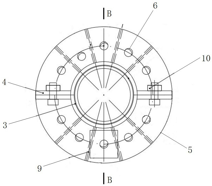
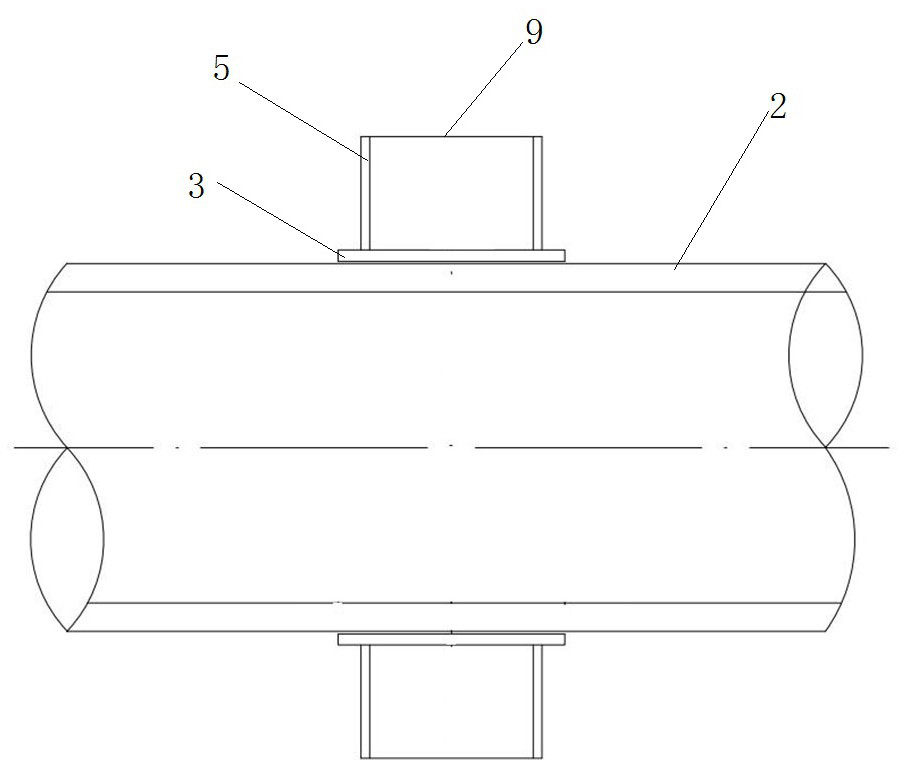
[0031] like figure 1 As shown, the weld-free network frame node reinforcement structure includes a pair of intermediate reinforcement hoops and a pair of tension components. There are two pairs of reinforcement hoops in the middle, which are correspondingly fastened on the two grid tie rods 2 at the radial sides of the same middle bolt ball 1 and at an angle of 180°. like figure 2 , image 3 and Figure 4 As shown, the middle reinforcement hoop pair includes two hoops with the same structure, and each hoop includes a semi-arc hoop plate 3, a flange 4 welded to the radial ends of the semi-arc hoop plate 3 and welded joints. Flange connection plates 5 on both axial sides of the semi-arc hoop plate 3 . Wherein, the inner diameter of the semi-arc hoop 3 is the same as the radius of the grid tie rod 2 to be tightened, the wing 4 is parallel to the axis of the semi-arc hoop 3, and each wing 4 is provided with two spacers. Arranged bolting holes. The flange connecting plate 5 ...

Embodiment 2

[0037] like Figure 5 , Figure 6 and Figure 7 As shown, the welding-free network frame node reinforcement structure of this embodiment includes a pair of end reinforcement hoops and a reinforcement steel wire rope 18 to reinforce the connection node with the end bolt ball 11 of the steel network structure. There is a pair of end reinforcing hoops, which are used to tighten on the grid tie rods 12 connected with the end bolt balls 11, including two hoops with the same structure, and each hoop includes a semi-arc hoop plate 13 , the wing plates 14 connected to the radial ends of the semi-arc hoop 13 and the flange connecting plates 15 welded to the axial sides of the semi-arc hoop 13, the semi-arc hoop 13, the wing 14 and the flange The structure of the flange connecting plate 15 and the connection relationship between the three are the same as the structure of the semi-arc hoop plate 3, the wing plate 4 and the flange connection plate 5 in the above-mentioned embodiment 1 a...


PUM


Abstract

The invention relates to a welding-free net rack node reinforcing structure and belongs to the technical field of steel net rack structure reinforcing. The welding-free net rack node reinforcing structure comprises two middle reinforcing hoop pairs and opposite-pulling assemblies or comprises an end-reinforced hoop pair and a reinforcing steel wire rope, the middle reinforcing hoop pairs are hooped on two net rack pull rods arranged on two radial sides of a bolt ball and form an angle of 180 degrees respectively, the opposite-pulling assemblies comprise opposite-pulling screw rods and fastening nuts in threaded connection with the opposite-pulling screw rods, and the middle reinforcing hoop pairs and the opposite-pulling assemblies form a middle node reinforcing structure; and the end-reinforced hoop pair is used for being hooped on the net rack pull rods connected with a bolt ball at an end of a steel net rack structure, the reinforcing steel wire rope surrounds the bolt ball, two ends of the reinforcing steel wire rope are fixedly connected with the end-reinforced hoop pair so as to be in a tightened state, and the end-reinforced hoop pair and the reinforcing steel wire rope form an end node reinforcing structure. Connecting joints of the bolt ball are reinforced in a welding-free mode, and firmness and safety of the connecting joints are guaranteed.

Description

technical field [0001] The invention relates to the technical field of steel grid structure reinforcement, in particular to a welding-free grid node reinforcement structure. Background technique [0002] The steel grid structure is a space structure composed of multiple rods connected through nodes according to a certain grid form. It has the advantages of small space force, light weight, high rigidity, and good seismic performance. It can be used as a gymnasium, theater, theater, etc. Roofs for exhibition halls, waiting halls, stadium stand awnings, hangars, two-way large column distance frames, etc. [0003] During the actual use of the steel grid structure, due to factors such as function changes and decoration, the actual load may exceed the original design load of the grid, so it needs to be reinforced. Traditional steel grids generally have two types of welded ball joints and bolted ball joints. For the welded ball node grid, it can generally be reinforced by welding...

Claims


Application Information

Patent Timeline
Patent Type & Authority Applications(China)
IPC IPC(8): E04B1/58E04B1/34E04G23/02
CPCE04B1/58E04B1/34E04G23/0218
Inventor 卢春亭张祥伟刘会超梁波强梁永灿周楷夏仲锐胡惠丽王振现张向
Owner CHINA CONSTR SENVENTH ENG BUREAU INSTALLATION ENG
Why Eureka
Try Eureka