Abrasion compensation device of driving disc brake and self-compensation method of abrasion compensation device

A disc brake and wear compensation technology, applied in brake actuators, slack adjusters, gear shifting mechanisms, etc., can solve the problems of being easily disturbed by the external environment, high maintenance and operation costs, low automation level, etc. Maintenance time, small overall size, stable and continuous effect of piston return force

Pending Publication Date: 2021-10-22
CRRC QISHUYAN INSTITUTE CO LTD
View PDF5 Cites 1 Cited by
  • Summary
  • Abstract
  • Description
  • Claims
  • Application Information

AI Technical Summary

Problems solved by technology

[0003] Existing wear compensation devices generally require frequent measurements manually or by sensors to obtain the wear amount of the friction disc, and then further perform wear compensation according to the wear amount. Usually, the automation level is low, the maintenance and operation cost is high, and it is easily affected by the external environment. interfere with safety hazards

Method used


Image

  • Abrasion compensation device of driving disc brake and self-compensation method of abrasion compensation device
  • Abrasion compensation device of driving disc brake and self-compensation method of abrasion compensation device
  • Abrasion compensation device of driving disc brake and self-compensation method of abrasion compensation device

Examples


Embodiment Construction

[0044] In the following description, numerous specific details are given in order to provide a more thorough understanding of the present invention. It will be apparent, however, to one skilled in the art that the present invention may be practiced without one or more of these details. In other examples, some technical features known in the art are not described in order to avoid confusion with the present invention.

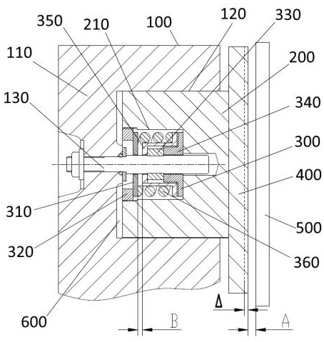
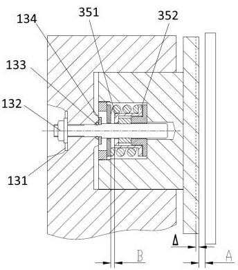
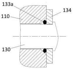
[0045] See attached Figures 1 to 7 , a wear compensation device for a driving disc brake, wherein the brake includes: a caliper body 100, a body portion 110, a first installation space 120, a fixing rod 130, a lock washer 131, a mounting nut 132, a sealing ring 133, Seal pressing plate 134, corner seal 133a, piston 200, second installation space 210, compensation device 300, spring pressing plate 310, fixing nut 320, adjusting expansion sleeve 330, adjusting bushing 340, spring guide sleeve 350, external thread 321, installation groove 322, iron wire 323, thr...


PUM


Abstract

The invention discloses an abrasion compensation device of a driving disc brake and a self-compensation method of the abrasion compensation device, and belongs to the field of brakes. The compensation device is arranged on a fixing rod and is suitable for adjusting the relative position between a clamp body and a piston; and the abrasion compensation device comprises a spring pressing plate, a fixing nut, an adjusting expansion sleeve, and adjusting lining, a spring guide sleeve and an elastic piece, wherein the spring pressing plate is installed on the fixing rod in a sliding mode, the fixing nut is installed on the inner wall of the piston in an interference mode and is suitable for limiting the position of the spring pressing plate, the adjusting expansion sleeve is in interference fit with the fixing rod, the adjusting lining is arranged on one side of the adjusting expansion sleeve and is in an L shape, the spring guide sleeve is placed on the adjusting expansion sleeve and the adjusting lining, one end of the elastic piece is arranged on the spring guide sleeve, and the other end of the elastic piece is connected with the spring pressing plate. The piston is pressed back through the elastic piece, it is guaranteed that a friction plate cannot be in dragging abrasion with the brake disc, and therefore the situation that a brake sealing failure is caused by continuous heat generation, and driving safety is caused is avoided.

Description

technical field [0001] The invention belongs to the field of brakes, in particular to a wear compensation device for a driving disc brake and a self-compensation method thereof. Background technique [0002] A disc brake includes a power source, a transmission component for motion transmission power, and a friction plate that is used to offset the brake disc to achieve the braking effect. Common transmission components include: piston push rod, gear transmission, etc. Dry friction plates will wear out after long-term use. If there is no automatic wear compensation, it will inevitably cause system response delay, vehicle braking distance to be extended, and running stability to be reduced. Adding an automatic wear compensation device can change the initial position of the brake piston to ensure that the stroke of the piston is always consistent, so that the vehicle can always maintain good braking performance. [0003] Existing wear compensation devices generally require fr...

Claims


Application Information

Patent Timeline
Patent Type & Authority Applications(China)
IPC IPC(8): F16D65/52F16D65/18F16D121/04F16D125/06F16D125/08
CPCF16D65/52F16D65/18F16D2121/04F16D2125/06F16D2125/08
Inventor 孙龙跃王能刘宇陈学伟王阳
Owner CRRC QISHUYAN INSTITUTE CO LTD
Why Eureka
Try Eureka