
Brake with self-compensation function and braking method thereof

A kind of brake and self-compensation technology, applied in the direction of brake type, axial brake, brake components, etc., can solve the problems of not suitable for space-constrained occasions, transmission components are prone to wear, and one-side transmission line is long, etc., to avoid Unable to adjust, avoid waste of braking force, safe and reliable power source

Pending Publication Date: 2021-10-08
CRRC QISHUYAN INSTITUTE CO LTD
View PDF9 Cites 5 Cited by
  • Summary
  • Abstract
  • Description
  • Claims
  • Application Information

AI Technical Summary

Problems solved by technology

[0003] After carefully studying the existing technology, the inventor found that the existing brake has at least the following technical defects: 1. The overall structure is relatively complicated, with many transmission parts and long axial dimension, which is not suitable for space-limited occasions; 2. The transmission components It is prone to wear and tear, and when the transmission parts are worn out, the reliability of the brake will be greatly reduced, and it is difficult to achieve self-compensation; 3. Since the power and compensation mechanism of the existing brake comes from one side, the other side is passively attached to and compensation, the transmission route on one side is longer, which not only puts forward relatively high requirements on the transmission mechanism, but also is prone to partial wear

Method used


Image

  • Brake with self-compensation function and braking method thereof
  • Brake with self-compensation function and braking method thereof
  • Brake with self-compensation function and braking method thereof

Examples


Embodiment Construction

[0044] In the following description, numerous specific details are given in order to provide a more thorough understanding of the present invention. It will be apparent, however, to one skilled in the art that the present invention may be practiced without one or more of these details. In other examples, some technical features known in the art are not described in order to avoid confusion with the present invention.

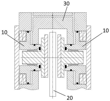
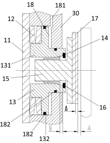
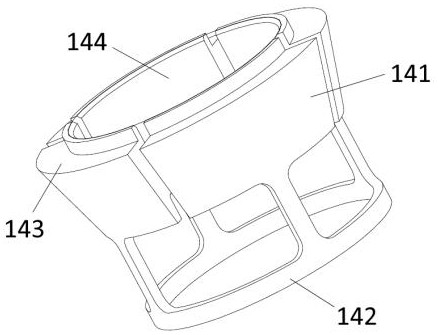
[0045] See attached Figures 1 to 5 , a brake with self-compensation, the brake includes: a caliper body 30, a brake unit 10 arranged on both inner sides of the caliper body 30, and a brake disc 20 arranged in the middle of the brake unit 10. Wherein, the brake unit 10 includes: a baffle plate 11, a disc spring 12, a piston 13, an adjusting taper sleeve 14, a piston push rod 15, a retaining ring 16, a friction plate 17, a hydraulic oil chamber 18, a body part 131, and a mounting part 132 , the first tapered surface 133 , the second tapered surface 141 , the an...


PUM


Abstract

The invention discloses a brake with a self-compensation function and a braking method of the brake, and belongs to parking braking equipment. The brake comprises a brake disc and brake units arranged on the two sides of the brake disc, each brake unit comprises baffles, a piston, an adjusting taper sleeve, a piston push rod and a friction plate, a caliper body and the baffles form an annular mounting space, a piston can axially moving left and right along the annular mounting space, the adjusting taper sleeve is arranged on the side, away from the baffles, of the inner surface of the piston in a sleeving mode and can be kept expanding or contracting in the radial direction of the mounting space, one end of the piston push rod is mounted on the adjusting taper sleeve in a sleeving manner, the piston push rod is in clearance fit or interference fit with the adjusting taper sleeve, and the friction plate is connected with the other end of the piston push rod and is suitable for pressing the brake disc. The brake belongs to a fixed parking brake, the pressing force of a disc spring is completely converted into the parking braking force through hydraulic oil return, and due to the fact that the parking braking force is not consumed by other parts, the braking efficiency is high, an external power source is not needed, and automatic abrasion compensation can be achieved.

Description

technical field [0001] The invention belongs to parking brake equipment, in particular to a brake with self-compensation and a braking method thereof. Background technique [0002] At present, most of the floating parking clamps are on the market, such as: a disc brake with parking brake (CN201322072), a hydraulic disc brake with parking brake (CN204284270U), clamp disc parking Brake (CN2813385), caliper parking brake (CN103573868 A). [0003] After carefully studying the existing technology, the inventor found that the existing brake has at least the following technical defects: 1. The overall structure is relatively complicated, with many transmission parts and long axial dimension, which is not suitable for space-limited occasions; 2. The transmission components It is prone to wear and tear, and when the transmission parts are worn out, the reliability of the brake will be greatly reduced, and it is difficult to achieve self-compensation; 3. Since the power and compensat...

Claims


Application Information

Patent Timeline
Patent Type & Authority Applications(China)
IPC IPC(8): F16D55/22F16D65/095F16D65/14F16D65/72F16D121/04
CPCF16D55/22F16D65/095F16D65/14F16D65/72F16D2121/04F16D2127/06
Inventor 孙龙跃王阳王能陈学伟刘宇
Owner CRRC QISHUYAN INSTITUTE CO LTD
Learn More