Optical lens and imaging equipment
An optical lens and lens technology, which is applied in the field of optical lenses, can solve the problems of unsatisfactory zoom lens imaging effects, etc., and achieve the effects of improving camera experience, shortening axial length, and effectively utilizing space
- Summary
- Abstract
- Description
- Claims
- Application Information
AI Technical Summary
Problems solved by technology
Method used
Image

Examples
Embodiment approach
[0043] As an implementation, the optical lens satisfies the following conditional formula:
[0044] 1.5
[0045] Wherein, AC34 represents the air gap distance between the third lens and the fourth lens on the optical axis, and CT4 represents the lens thickness of the fourth lens on the optical axis.
[0046] When the conditional formula (1) is satisfied, when 1.5<AC34 / CT4, by reasonably configuring the air gap between the third lens and the fourth lens, the light deflection tends to be slow, and the optical system can be increased to a certain extent Effective focal length, so as to achieve the effect of telephoto telephoto, at the same time, it can control the thickness difference of the fourth lens, so as to avoid the deformation of the lens due to uneven cooling after the lens is formed due to the excessive thickness of the fourth lens, and it is helpful for the production and forming of the lens; when When AC34 / CT4<3.0, it can well control the angle of l...
no. 1 example
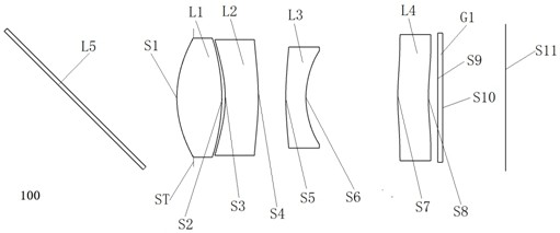
[0092] Please refer to figure 1 , which is a schematic structural view of the optical lens 100 provided by the first embodiment of the present invention, the optical lens 100 includes in sequence from the object side to the image side along the optical axis: a prism L5 with a reflective surface, a stop ST, a first lens L1, the second lens L2, the third lens L3, the fourth lens L4 and the filter G1.
[0093] Wherein, the prism L5 can be a right-angle prism or other type of prism to realize light deflection and enter the first lens L1;
[0094] The diaphragm ST is set in front of the first lens L1 to reduce stray light;
[0095] The first lens L1 is a plastic aspheric lens with positive refractive power, the object side S1 of the first lens is convex, and the image side S2 of the first lens is convex;
[0096] The second lens L2 is a plastic aspheric lens with negative refractive power, the object side S3 of the second lens is concave, and the image side S4 of the second lens...
no. 2 example
[0106] For the structural schematic diagram of the optical lens 200 provided in this embodiment, please refer to Image 6 Compared with the optical lens 100 in the first embodiment, the structure of the optical lens 200 in this embodiment has little change, and the biggest change is the distance from the second lens to the third lens.
[0107] Specifically, the optical lens 200 sequentially includes: a prism L5 with a reflective surface, a stop ST, a first lens L1, a second lens L2, a third lens L3, and a fourth lens L4 from the object side to the image side along the optical axis direction. and filter G1.
[0108] Wherein, the prism L5 can be a right-angle prism or other type of prism to realize light deflection and enter the first lens L1;
[0109] The diaphragm ST is set in front of the first lens L1 to reduce stray light;
[0110] The first lens L1 is a plastic aspheric lens with positive refractive power, the object side S1 of the first lens is convex, and the image side ...
PUM
 Abstract
Description
Claims
Application Information
 - R&D
- Intellectual Property
- Life Sciences
- Materials
- Tech Scout
- Unparalleled Data Quality
- Higher Quality Content
- 60% Fewer Hallucinations
Browse by: Latest US Patents, China's latest patents, Technical Efficacy Thesaurus, Application Domain, Technology Topic, Popular Technical Reports.
© 2025 PatSnap. All rights reserved.Legal|Privacy policy|Modern Slavery Act Transparency Statement|Sitemap|About US| Contact US: help@patsnap.com