
Optical assembly, display system and manufacturing method

A manufacturing method and technology of optical components, applied in the direction of optical components, optics, instruments, etc., can solve the problems of large lens group volume, etc., achieve the effect of small component volume, reduce production cost, and facilitate manufacturing process

Pending Publication Date: 2021-10-22
蒋晶
View PDF11 Cites 0 Cited by
  • Summary
  • Abstract
  • Description
  • Claims
  • Application Information

AI Technical Summary

Problems solved by technology

The lens group of this solution is large in volume, and the half-transparent and half-mirror will attenuate the brightness of the ambient light by half. Realizing a compact display module with a large field of view that does not attenuate the ambient light is an important problem that needs to be solved urgently in retinal imaging technology.

Method used


Image

  • Optical assembly, display system and manufacturing method
  • Optical assembly, display system and manufacturing method
  • Optical assembly, display system and manufacturing method

Examples


Embodiment Construction

[0161] In the following, only some exemplary embodiments are briefly described. As those skilled in the art would realize, the described embodiments may be modified in various different ways, all without departing from the spirit or scope of the present disclosure. Accordingly, the drawings and descriptions are to be regarded as illustrative in nature and not restrictive.

[0162] The flowchart and block diagrams in the Figures illustrate the architecture, functionality, and operation of possible implementations of apparatuses, methods and computer program products according to various embodiments of the present disclosure. In this regard, each block in the flowchart or block diagram may represent a module, program segment, or part of code that contains one or more logic functions for implementing predetermined Executable instructions for a function. It should also be noted that, in some alternative implementations, the functions noted in the block may occur out of the order...


PUM


Abstract

The invention relates to a manufacturing method of an optical element. The method comprises the steps that: a light conduction medium is provided, wherein the light conduction medium is provided with a first surface and a second surface which are not parallel to each other, a first photosensitive film / first photosensitive plate is located on the first surface, and a second photosensitive film / second photosensitive plate is located on the second surface; laser is emitted by using a laser; the laser is split into a first laser beam and a second laser beam; the first laser beam is split into a third laser beam and a fourth laser beam; the third laser beam is converged to a first point outside the light conduction medium, and the third laser beam is emitted from the first point to the first photosensitive film / first photosensitive plate; the fourth laser beam is converged to a second point outside the light conduction medium, and the fourth laser beam is emitted from the second point to the first photosensitive film / first photosensitive plate; and the third laser beam converged to the first point and the fourth laser beam converged to the second point generate interference exposure in the photosensitive material of the first photosensitive film / first photosensitive plate, so that a first volume holographic optical element is obtained.

Description

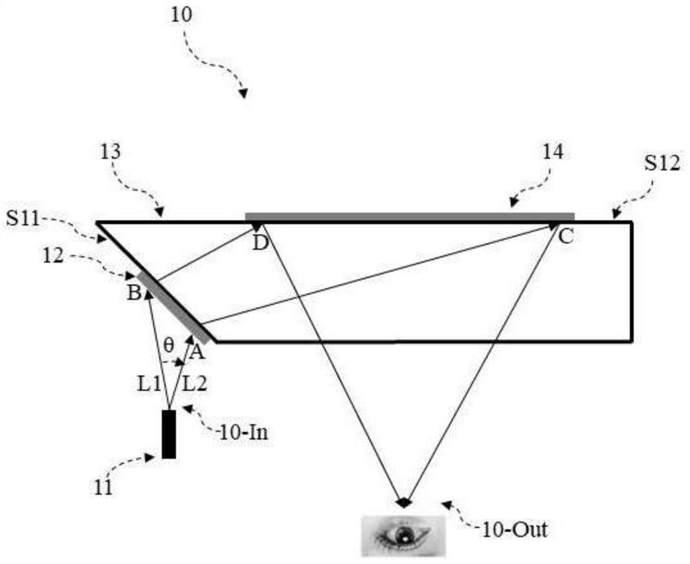
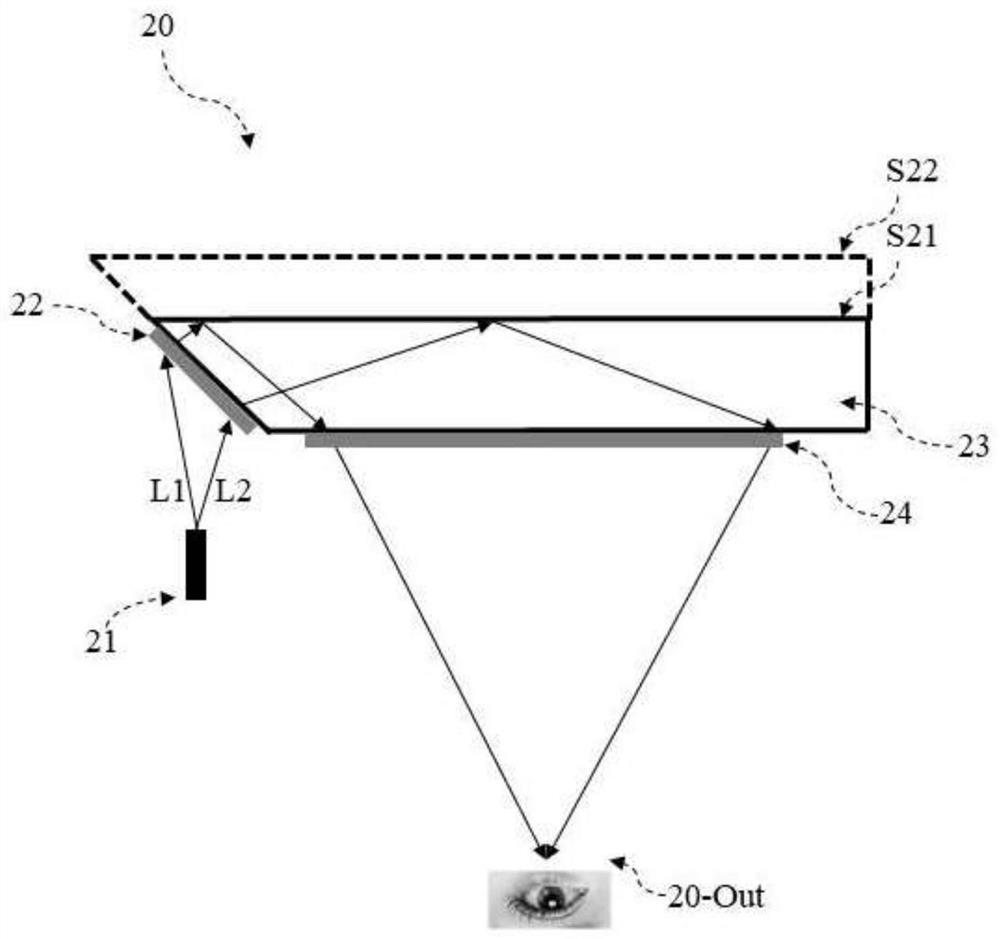
technical field [0001] The present disclosure generally relates to the field of optical display, and in particular to an optical component without imaging distortion based on trapezoidal back projection compensation, a display system and a manufacturing method. Background technique [0002] With the development of computer technology and display technology, virtual reality (Virtual Reality, VR) technology to experience the virtual world through computer simulation system, and augmented reality (Augmented Reality, AR) technology and hybrid technology to integrate display content into real environment background. Reality (Mixed Reality, MR) technology has developed rapidly. [0003] Near-eye VR, AR and MR display technologies that combine the aforementioned VR, AR and MR technologies with near-eye displays are important new display technologies that can bring unprecedented visual experience and human-computer interaction to people. Near-eye VR display mainly pursues immersive...

Claims


Application Information

Patent Timeline
IPC IPC(8): G02B27/10G02B27/01G02B27/42G02B5/32
CPCG02B27/1006G02B27/0172G02B27/4272G02B5/32G02B2027/0174Y02P70/50
Inventor 杨鑫黄正宇
Owner 蒋晶
Learn More