Eureka AIR delivers breakthrough ideas for toughest innovation challenges, trusted by R&D personnel around the world.

3D light field conversion method and device

A conversion method, 3D technology, applied in the field of 3D display, can solve the problems of high price, complex structure, expensive off-axis camera array, etc., and achieve the effect of low fraud and simple structure

Pending Publication Date: 2021-11-12
深圳臻像科技有限公司
View PDF0 Cites 0 Cited by
  • Summary
  • Abstract
  • Description
  • Claims
  • Application Information

AI Technical Summary

Problems solved by technology

The off-axis camera structure has a large public scene area and no trapezoidal distortion, but the structure is complex and expensive, and the off-axis camera array is even more expensive

Method used


Image

  • 3D light field conversion method and device
  • 3D light field conversion method and device
  • 3D light field conversion method and device

Examples


Embodiment Construction

[0042] The following will clearly and completely describe the technical solutions in the embodiments of the present invention with reference to the accompanying drawings in the embodiments of the present invention. Obviously, the described embodiments are only some, not all, embodiments of the present invention. Based on the embodiments of the present invention, all other embodiments obtained by persons of ordinary skill in the art without making creative efforts belong to the protection scope of the present invention.

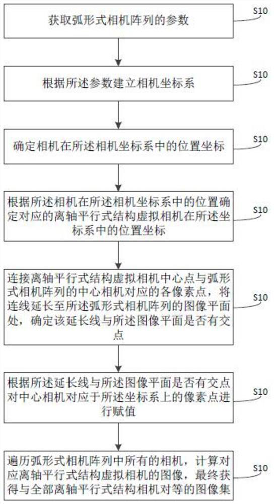
[0043] refer to figure 1 , the present embodiment provides a method for converting a 3D light field, which specifically includes the following steps:

[0044] S10: Obtain parameters of an arc-shaped camera array; wherein, the parameters include the number of cameras of the arc-shaped camera array, the working distance, field of view, and resolution of the cameras of the camera array;

[0045] S20: Establish a camera coordinate system according to the paramete...


PUM


Abstract

The invention discloses a 3D light field conversion method and device, and the method comprises the steps: obtaining the parameters of an arc-shaped camera array; establishing a camera coordinate system according to the parameters; determining position coordinates of a camera in the camera coordinate system; determining position coordinates of a corresponding off-axis parallel structure virtual camera in the coordinate system according to the position of the camera in the camera coordinate system; connecting the central point of the off-axis parallel structure virtual camera with each pixel point corresponding to the central camera of the arc-shaped camera array, and extending a connecting line to an image plane of the arc-shaped camera array; and assigning a value to a pixel point, corresponding to the coordinate system, of a central camera according to whether the extension line and the image plane have an intersection point or not. According to the conversion method, the camera array of the arc-shaped center camera structure is used for collecting the image of the 3D model or the scene, and the image is converted into the image corresponding to the off-axis camera structure, so that the existing arc-shaped camera structure does not generate trapezoidal distortion.

Description

technical field [0001] The invention relates to the technical field of 3D display, in particular to a method and device for converting a 3D light field. Background technique [0002] A stereo camera is a camera array composed of two or more cameras with the same specifications and parameter settings. When making a stereoscopic imaging data source for a 3D display system, it is necessary to use a camera array to perform multi-directional synchronous rendering or acquisition of a 3D model or real scene, so as to obtain multiple parallax images. [0003] According to the camera array layout, the camera array layout structures mainly include parallel, convergent, off-axis parallel and arc forms. In an integrated imaging 3D display system, an off-axis parallel structure is generally used for rendering in 3D modeling software. However, in most actual 3D modeling acquisition systems, an arc structure is generally adopted. [0004] In the arc structure, the camera array is arrang...

Claims


Application Information

Patent Timeline
Patent Type & Authority Applications(China)
IPC IPC(8): H04N17/00G06F17/16H04N13/261H04N13/275
CPCH04N17/002G06F17/16H04N13/261H04N13/275
Inventor 徐文宇李沛吴英黄辉
Owner 深圳臻像科技有限公司
Why Eureka
Eureka Blog
Learn More