FLASH chip detection equipment

A chip detection and equipment technology, applied in the detection field, can solve the problems of single function, inconvenient use, inaccurate high temperature detection, etc., to improve work efficiency, avoid contact damage, and save detection time.

Active Publication Date: 2021-10-22
西安环宇芯微电子有限公司
View PDF8 Cites 1 Cited by
  • Summary
  • Abstract
  • Description
  • Claims
  • Application Information

AI Technical Summary

Problems solved by technology

[0004] The technical problem solved by the present invention is to overcome the shortcomings of the prior art such as single function, inconvenient use, inaccurate high temperature resistance detection, etc., and provide a FLASH chip detection device

Method used


Image

  • FLASH chip detection equipment
  • FLASH chip detection equipment
  • FLASH chip detection equipment

Examples


Embodiment Construction

[0022] The following will clearly and completely describe the technical solutions in the embodiments of the present invention with reference to the accompanying drawings in the embodiments of the present invention. Obviously, the described embodiments are only some, not all, embodiments of the present invention. Based on the embodiments of the present invention, all other embodiments obtained by persons of ordinary skill in the art without making creative efforts belong to the protection scope of the present invention.

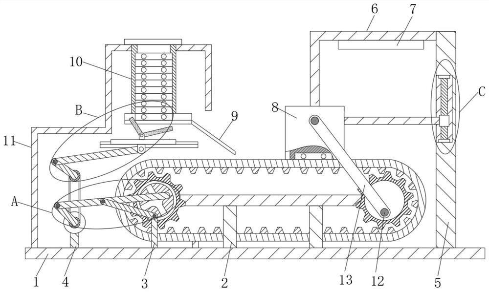
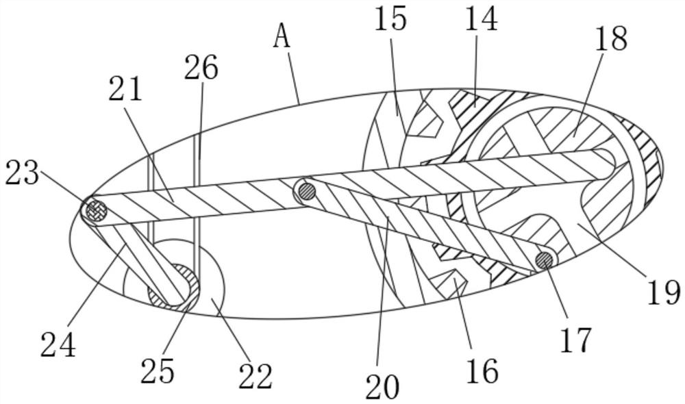
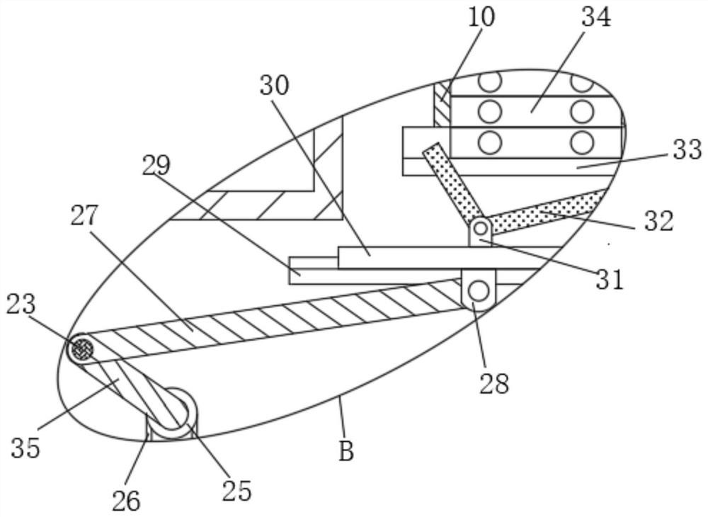
[0023] see Figure 1-7 , the present invention provides a technical solution: a FLASH chip detection device in this embodiment, including a base 1, characterized in that: the base 1 is fixedly provided with a support frame 2, and the two ends of the support frame 2 are respectively movably socketed Gear 14 is arranged, and the front of gear 14 is fixedly connected with fixed plate 18, and the front of this fixed plate 18 is provided with track groove 19; The ...


PUM


Abstract

Disclosed is FLASH chip detection equipment comprises a base, the top end of the base is fixedly connected with a supporting frame, the two ends of the supporting frame are movably sleeved with gears respectively, the front faces of the gears are fixedly connected with fixing discs, rail grooves are formed in the front faces of the fixing discs, and the outer portions of the gears at the two ends are movably sleeved with a conveying belt; tooth blocks are fixedly distributed on the inner wall of the conveying belt at equal intervals, the conveying belt is in gear meshing connection with the gear through the tooth blocks, and a motor, a third supporting rod, a movable stud, a second supporting rod, a first supporting rod, the gear and the fixing disc are arranged for transmission in a matched mode, so that the second supporting rod rotates in a rail groove in the fixing disc; therefore, the gear intermittently drives the gear block and the conveying belt to operate, the purpose of intermittent and pause transmission of the conveying belt is achieved, detection time is provided for chip conveying detection in the later period, and the working efficiency is improved.

Description

technical field [0001] The invention relates to the technical field of detection, in particular to a FLASH chip detection device. Background technique [0002] FLASH chips are widely used storage materials, and RAM chips are easily confused with them. We often talk about these two chips in articles about IT. Due to their different working conditions and methods, their performance and usage are also different. [0003] The detection equipment refers to the performance detection of various aspects of the chip, and the high temperature resistance detection of the chip is particularly important. Technical high-temperature resistance detection mostly uses manual picking and one-to-one high-temperature baking, which cannot achieve batch high-temperature processing, and the work efficiency is low. The condition of damage will affect the detection results of high temperature, and there is inaccuracy. Contents of the invention [0004] The technical problem solved by the inventi...

Claims


Application Information

Patent Timeline
Patent Type & Authority Applications(China)
IPC IPC(8): G11C29/50G11C29/08G11C29/56
CPCG11C29/50G11C29/08G11C29/56
Inventor 李昊天王登辉
Owner 西安环宇芯微电子有限公司
Why Eureka
Try Eureka