Cable reeling device

A cable reel and cable technology, applied in the direction of transportation and packaging, delivery of filamentous materials, thin material processing, etc., can solve the problems of time delay, need to replace the cable reel, waste of labor, etc., and achieve the effect of reducing the number of replacements

Inactive Publication Date: 2021-10-26
EJIN HORO BANNER WANQI MACHINING CO LTD
View PDF5 Cites 0 Cited by
  • Summary
  • Abstract
  • Description
  • Claims
  • Application Information

AI Technical Summary

Problems solved by technology

Manually rewinding the cable is a waste of manpower and time
To take up the cable with the mining cable take-up machine, the cable take-up reel needs to be replaced, which wastes manpower and time

Method used


Image

  • Cable reeling device
  • Cable reeling device
  • Cable reeling device

Examples


Embodiment 1

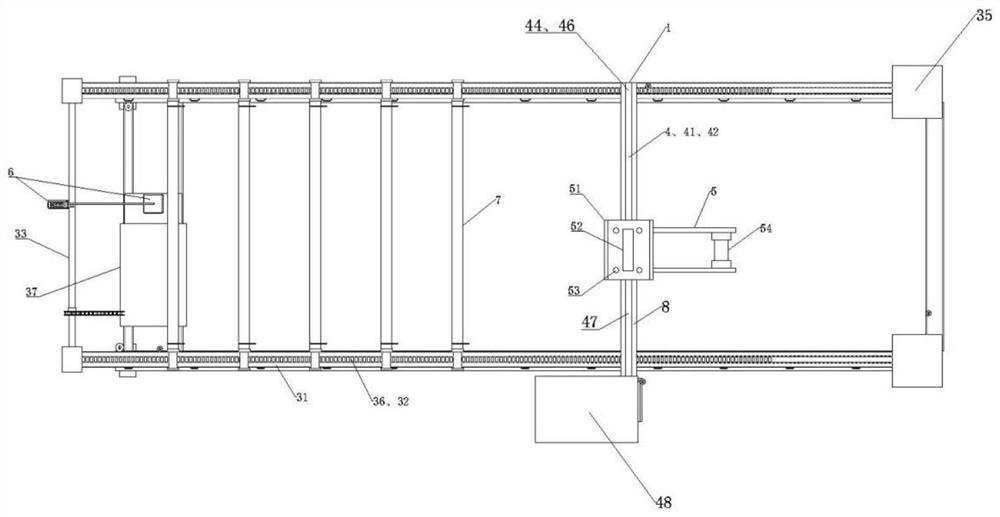
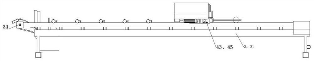
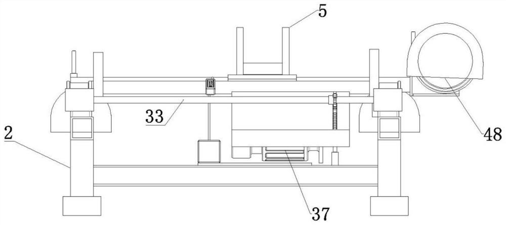
[0022] Example 1, such as Figure 1-3 As shown, a cable coiling device, the device (1) is arranged above a movable cable reel through a bracket (2), and the device (1) includes a longitudinal The drive unit (3), the transverse drive unit (4) capable of longitudinal movement on the longitudinal drive unit (3), the cable guide unit (5) capable of transverse movement on the transverse drive unit (4) and the longitudinal A drive controller (6) for the operation of the drive unit (3) and the transverse drive unit (4). The above-mentioned device (1) is set above a movable cable reel through the bracket (2), which belongs to the situation that the cable coiling area is not large enough. At this time, a movable cable reel passes through the device in the cable coiling area Carry out cable reeling, when the cable reel is full, push the movable cable reel full of cables away from the cable reel area, replace another movable cable reel and continue the cable reel, in this way, replace t...

Embodiment 2

[0023] Example 2, such as Figure 1-3 As shown, a cable coiling device, the device (1) is arranged above a plurality of fixed cable reels through a bracket (2), and the device (1) includes a longitudinal The drive unit (3), the transverse drive unit (4) capable of longitudinal movement on the longitudinal drive unit (3), the cable guide unit (5) capable of transverse movement on the transverse drive unit (4) and the longitudinal A drive controller (6) for the operation of the drive unit (3) and the transverse drive unit (4). The above-mentioned device (1) is arranged above a plurality of fixed cable reels through the bracket (2), which belongs to the situation that the cable coiling area is large enough. At this time, multiple cable reels are fixed in the cable coiling area and pass through the device Carry out the cable coiling work one by one, and leave the cable coiling area together after multiple cable drums are full of cables.

Embodiment 3

[0024] Example 3, such as Figure 1-3 As shown, the described longitudinal drive device (3) includes two longitudinal drive chain boxes (31) fixed on the two longitudinal beams (21) of the support (2) in a bolted manner, and each longitudinal drive chain The top of the box (31) is provided with a longitudinal guiding slit (32) along the longitudinal direction, a horizontal drive shaft (33) fixed on one end of the two longitudinal drive chain boxes (31) in a bearing connection mode, and in each longitudinal drive chain box Vertical driving sprocket (34) is respectively housed on the horizontal drive shaft (33) in (31), the longitudinal driven sprocket (35) that is fixed on the other end of two vertical driving chain boxes (31) with bearing connection mode, The vertical drive chain (36) that winds around each pair of corresponding vertical drive sprockets (34) and the vertical driven sprocket (35) and the vertical drive motor that drives the horizontal drive shaft (33) to rotate...


PUM


Abstract

The invention relates to a cable reeling device. The device is arranged above a cable drum through a support; and the device comprises a longitudinal driving device fixed on the support in a bolt connection mode, a transverse driving device capable of longitudinally moving on the longitudinal driving device, a cable guiding device capable of transversely moving on the transverse driving device, and a driving controller capable of correspondingly controlling the longitudinal driving device and the transverse driving device to operate. Under the control of the driving controller, the longitudinal driving device and the transverse driving device can coil the cable on the cable drum in the cable guiding device moving area through the cable guiding device, so that the replacement frequency of the cable drum which is fully wound with the cable can be greatly reduced; and even the problem of cable winding can be solved at one time without replacing the cable drum which is fully wound with the cable.

Description

technical field [0001] The invention relates to a cable reeling device. Background technique [0002] Mining cables refer to the cables used for ground equipment and underground equipment in coal mining, including cables for coal mining machines, conveyors, communications, lighting and signal equipment. [0003] When mining cables need to be replaced, maintained, or rearranged, the cables are usually wound up manually or by a mining cable winding machine. Manual winding of cables is a waste of manpower and time. To take up the cable with the mining cable take-up machine, the cable take-up reel needs to be replaced, which wastes manpower and time. Contents of the invention [0004] The purpose of the present invention is to overcome the disadvantages of the prior art and provide a device capable of stacking mining cables on a movable cable reel or on multiple fixed cable reels. When the cable coiling area is not large enough, a movable cable reel can be moved to the cabl...

Claims


Application Information

Patent Timeline
Patent Type & Authority Applications(China)
IPC IPC(8): B65H67/04B65H54/28B65H67/052
CPCB65H67/0405B65H54/2821B65H67/052B65H67/0411B65H67/0417B65H2701/34
Inventor 赵云飞贺长春高冲祁凤荣
Owner EJIN HORO BANNER WANQI MACHINING CO LTD
Why Eureka
Try Eureka