Aluminum rod piece forming machining device

A technology for forming and processing rods, applied in the field of press brakes, can solve the problems of poor forming effect, inconvenient production, affecting the quality of pipe bending and forming, and achieve the effect of facilitating bending and forming

Active Publication Date: 2021-10-29
嘉兴赛德家具股份有限公司
View PDF7 Cites 3 Cited by
  • Summary
  • Abstract
  • Description
  • Claims
  • Application Information

AI Technical Summary

Problems solved by technology

However, during the molding production process, the pipe is easy to sink into the mold, and it is not easy to take out the pipe, which causes inconvenience in production
[0003]The production of some pipes only needs to bend the pipes to form an arc to meet the production size requirements, and does not need to form a relatively complicated structure, so in order to increase Convenience in production and use, using an upper mold with an arc structure; only two support blocks are used for support at the lower part, and during the pressing process, the middle part of the pipe is pressed through the downwardly protruding arc upper mold, because there is no support in the middle of the pipe The support of the block is used to bend the pipe. After the upper die is fully pressed down, the bent pipe can be obtained. Compared with the upper and lower dies, the operation is more convenient; but in the forming process, the bending force on the pipe Only in the middle position of the pipe, the middle position can meet the bending requirements, but the forming effect of the two ends of the pipe is poor, especially at the two ends of the support block. When pressing down, the two ends of the pipe cannot be completely fitted under the upper mold Surface, resulting in poor bending and forming effect at this part, affecting the bending and forming quality of the pipe

Method used


Image

  • Aluminum rod piece forming machining device
  • Aluminum rod piece forming machining device
  • Aluminum rod piece forming machining device

Examples


Embodiment 1

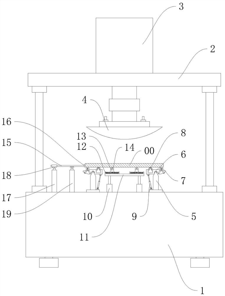
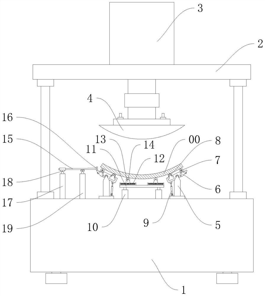
[0033] refer to Figure 1-3 As shown, this embodiment discloses an aluminum bar forming processing device, which includes a lower frame 1 and an upper frame 2, and a mold frame is installed between the lower frame 1 and the upper frame 2, and the mold frame is realized by a hydraulic rod. Up and down, the bending die 4 is installed on the lower part of the formwork, the structure of the bending die 4 can be selected and installed according to the parameters of the bending, and it is specifically an arc structure with the middle protruding downward and the two sides upward; Two main support components are installed on the frame 1 corresponding to the lower sides of the bending die 4. The support components can support the two ends of the aluminum rod 00, thereby forming a character-shaped force state with the upper bending die 4. The aluminum tube is bent; the distance between the two supporting components can be adjusted, and they are installed through different positions of s...

Embodiment 2

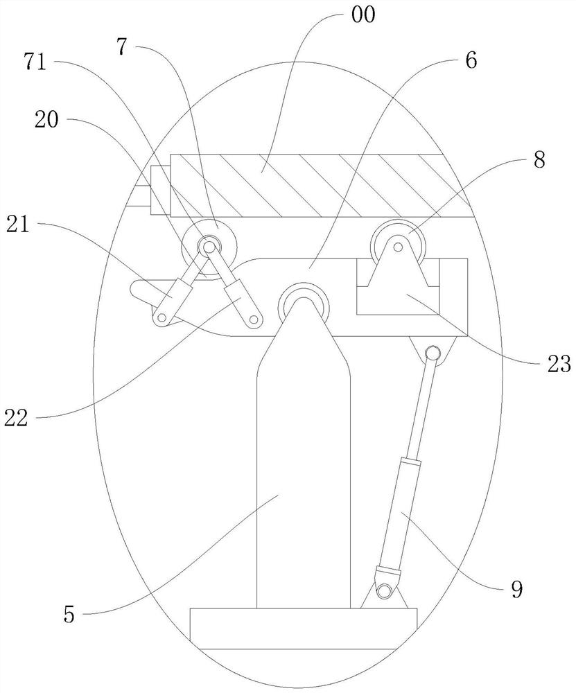
[0038] This embodiment discloses an aluminum rod forming processing device. On the basis of the embodiment, refer to Figure 1-4 As shown, the main support assembly is optimized so as to improve the bending effect on the end of the aluminum tube; in the main support assembly, the outer shaping roller 7 is located on the side away from the middle of the bending die 4, and the two sides of the outer shaping roller 7 The end is rotatably supported by the rotating seat 71, and is rotatably supported by the rotating member in the rotating seat 71; the height and position of the outer shaping roller 7 can be adjusted, specifically by adjusting the structure of the rotating seat 71.

[0039] The adjustment assembly includes two parts, push rod one 21 and push rod two 22. Push rod one 21 and push rod two 22 can adopt a telescopic structure, which can be provided by hydraulic pressure, pneumatic power, electric power or spring to realize telescopic. Push rod one 21 The fixed ends of pu...

Embodiment 3

[0044] This embodiment discloses a processing device for forming aluminum rods. On the basis of the above embodiments, the supporting structure of the aluminum tube is optimized and referred to Figure 5-8 Describe in detail; an auxiliary platform 11 that can be elastically lifted is set between the two main support components to form a pressure support for the middle part of the aluminum tube, so that the degree of fit between the aluminum tube and the bending die 4 can be maintained.

[0045] The auxiliary platform 11 is installed on the upper part of the lower frame 1 through several elastic lifting rods 10, and two sets of auxiliary support assemblies are installed on both sides of the auxiliary platform 11, and the two sets of auxiliary support assemblies can press and support the lower side of the aluminum rod 00, And they are respectively used to press against the positions on both sides of the lowest point of the bending die 4 of the support. When the bending die is pre...


PUM


Abstract

The invention discloses an aluminum rod piece forming machining device, relates to the technical field of bending presses, and aims at solving the problem of poor bending and shaping effect of aluminum rod pieces. The aluminum rod piece forming machining device is characterized by comprising a lower machine rack and an upper machine rack, wherein a bending die is installed on the upper machine rack through a hydraulic rod; two main supporting assemblies are arranged at two sides, corresponding to the lower side of the bending die, of the lower machine rack; each main supporting assembly comprises a supporting base used for supporting two ends of an aluminum rod; a supporting frame is hinged to each supporting base; and the supporting frames can reversely swing towards the two sides of the bending die. An outer shaping roller and an inner shaping roller are arranged in positions, corresponding to two sides of a hinging shaft, of the upper part of each supporting frame and are used for abutting against the lower side surface of the supporting aluminum rod. An elastic supporting piece is also comprised, and is used for elastically maintaining the supporting frame. The bending forming effect on an aluminum pipe is good, so that the curve formed by bending the aluminum pipe into an arc is smoother.

Description

technical field [0001] The invention relates to the technical field of press brakes, more specifically, it relates to an aluminum rod forming processing device. Background technique [0002] In the field of mechanical processing, it is often necessary to use a press brake to bend some workpieces. At present, the principle of the press brake is usually to place the aluminum tube on the lower die, and press down through the adapted lower die. Generate pressure to shape the aluminum tube on the mold, and the upper and lower molds work together to bend the aluminum tube. However, during the molding production process, the pipe is easily trapped in the mold, and it is not easy to take out the pipe, which causes inconvenience in production. [0003] The production of some pipes only needs to bend the pipes to form an arc, so that it meets the production size requirements and does not need to form a relatively complicated structure. Therefore, in order to increase the convenience ...

Claims


Application Information

Patent Timeline
Patent Type & Authority Applications(China)
IPC IPC(8): B21D7/06B21D43/00
CPCB21D7/06B21D43/003
Inventor 陆志强徐科学钟智伟
Owner 嘉兴赛德家具股份有限公司
Why Eureka
Try Eureka