A continuous molding method for thin terminals

A forming method and terminal technology, which are applied in the field of stamping processing, can solve the problems of structural deformation and easy punching of slender terminals, and achieve the effect of meeting the accuracy requirements.

Active Publication Date: 2022-01-07
苏州铭峰精密机械有限公司
View PDF7 Cites 0 Cited by
  • Summary
  • Abstract
  • Description
  • Claims
  • Application Information

AI Technical Summary

Problems solved by technology

The terminal is obtained from a metal strip with a thin sheet structure after multiple trimmings. If most of the outline of the terminal has been formed, then the end molding is not easy to handle, because the slender terminal structure will be produced when the end is pressed. deformation, and it is very difficult to carry out plastic positioning technology at this time
The thinner the terminal, the easier it is to break

Method used


Image

  • A continuous molding method for thin terminals
  • A continuous molding method for thin terminals
  • A continuous molding method for thin terminals

Examples


Embodiment

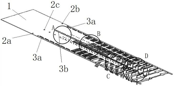
[0033] A thin terminal continuous molding method of the present invention, the steps include:

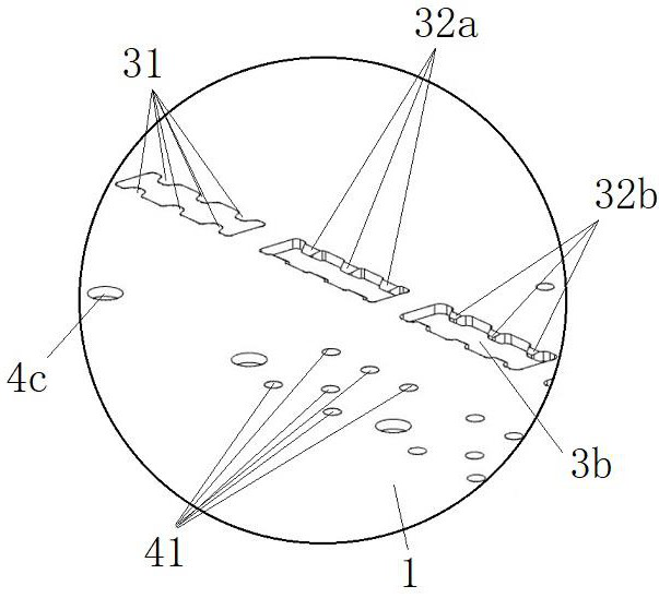
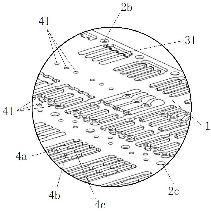
[0034] ① Use the head end and both sides of the metal strip 1 as the positioning, and cut out several positioning holes within the range of the processing unit. The design of the processing unit range includes an I-shaped connection reserve area and a product forming area between adjacent connection reserve areas. The positioning holes are located in the connection reserve area, and the product forming area is used to process terminal products. Such as figure 1 As shown, the positioning hole is used as the positioning datum during the stamping of the back section. The positioning holes include a first positioning hole 2a located on one side of the connecting reserved area, a second positioning hole 2b located on the other side of the connecting reserved area, and a third positioning hole 2c located in the middle of the connecting reserved area. The distance from the third position...


PUM

PropertyMeasurementUnit
heightaaaaaaaaaa
heightaaaaaaaaaa

Abstract

The invention belongs to the technical field of stamping processing, and relates to a continuous forming method for thin terminals. The steps include: ①punching positioning holes, ②end pre-cutting, ③end chamfering, ④end finishing, ⑤edge trimming, ⑥blanking; step② Based on the positioning hole, multiple pre-cut holes are cut in the product forming area. The pre-cut holes include side pre-cut holes near the side of the metal strip. The outline of the side pre-cut holes includes several side-by-side raised structures , the raised height of the raised structure does not exceed 2mm, and the raised structure is chamfered and refined before trimming. This method can preform the chamfered part at both ends of the terminal with a thinner size, and then punch the rest of the terminal contour. The process is continuous and ensures the structural accuracy of the terminal chamfer, which meets the customer's precision. Require.

Description

technical field [0001] The invention relates to the technical field of stamping processing, in particular to a thin terminal continuous forming method. Background technique [0002] Terminals are metal products used to connect different electronic components, and are generally relatively slender parts. For the convenience of insertion, the ends of the terminals are often formed into a truss structure with a smaller outer side. The terminal is obtained from a metal strip with a thin sheet structure after multiple trimmings. If most of the outline of the terminal has been formed, then the end molding is not easy to handle, because the slender terminal structure will be produced when the end is pressed. deformation, and it is very difficult to carry out plastic positioning technology at this time. The thinner the terminal, the easier it is to break. [0003] Therefore, it is necessary to design a new forming method to allow the terminal to obtain the desired structure quickl...

Claims


Application Information

Patent Timeline
Patent Type & Authority Patents(China)
IPC IPC(8): B21D35/00B21D43/00H01R43/16
CPCB21D35/002B21D43/003H01R43/16
Inventor 顾大明
Owner 苏州铭峰精密机械有限公司
Why Eureka
Try Eureka