
Support structure for three-dimensional (3D) printing platform part

A 3D printing and supporting structure technology, applied in the field of 3D printing, can solve the problems of inability to effectively control the shrinkage of thin layers, and achieve the effect of improving the initiation of constrained cracks, increasing the thickness, and enhancing the strength of the underlying structure

Pending Publication Date: 2019-04-12
上海汉邦联航激光科技有限公司
View PDF0 Cites 0 Cited by
  • Summary
  • Abstract
  • Description
  • Claims
  • Application Information

AI Technical Summary

Problems solved by technology

[0003] At present, when the conventional support structure generated when 3D printing the part model is used for the forming of large-scale platform parts, it cannot effectively improve the initiation of constrained cracks at the gap, and cannot effectively control the shrinkage of the initially formed thin layer.

Method used


Image

  • Support structure for three-dimensional (3D) printing platform part
  • Support structure for three-dimensional (3D) printing platform part
  • Support structure for three-dimensional (3D) printing platform part

Examples


Embodiment Construction

[0031] The specific embodiments of the present invention will be described in further detail below in conjunction with the accompanying drawings. These embodiments are only used to illustrate the present invention, but not to limit the present invention.

[0032] In the description of the present invention, it should be noted that the terms "center", "longitudinal", "transverse", "upper", "lower", "front", "rear", "left", "right", " The orientation or positional relationship indicated by "vertical", "horizontal", "top", "bottom", "inner", "outer", etc. are based on the orientation or positional relationship shown in the drawings, and are only for the convenience of describing the present invention and simplifying The description does not indicate or imply that the pointed device or element must have a specific orientation, be configured and operated in a specific orientation, and therefore cannot be understood as a limitation of the present invention. In addition, the terms "fir...


PUM


Abstract

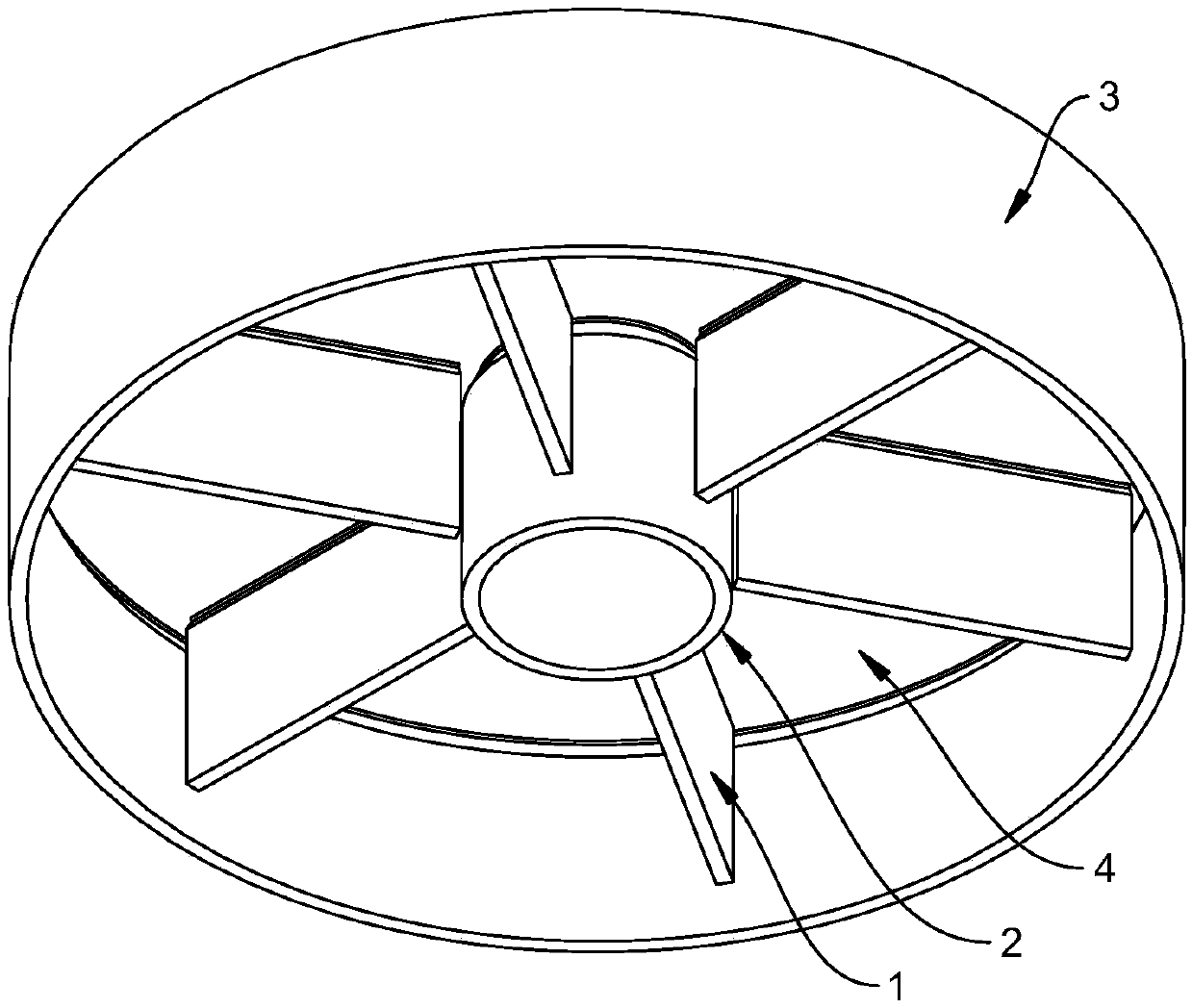
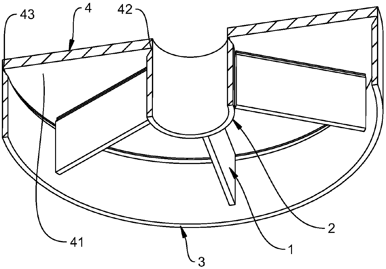
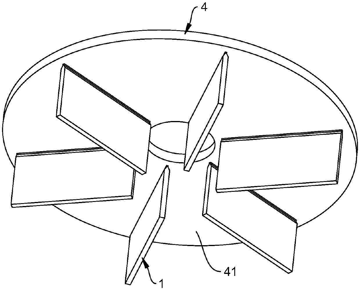
The invention relates to the technical field of three-dimensional (3D) printing, in particular to a support structure for a three-dimensional (3D) printing platform part. The support structure for the3D printing platform parts is arranged under the platform part, and comprises a platy support body, an inner edge annular support body and an outer edge annular support body, wherein the platy support body perpendicularly contacts the bottom surface of the platform part and is arranged along the radial direction of the bottom surface; the inner edge annular support body perpendicularly contacts the inner edge of the bottom surface of the platform part and is arranged along the circumferential direction of the inner edge; and the outer edge annular support body perpendicularly contacts the outer edge of the bottom surface of the platform part and is arranged along the circumferential direction of the outer edge. Through the platy support body, the platform part has high structural stiffness in the shrinkage trend direction, so that the heat shrinkage of a bottom layer of the platform part can be effectively controlled; and through the inner edge annular support body and the outer edgeannular support body, the thicknesses of the bottom layers of the platform part at the inner edge and the outer edge are increased, so that heat stress can be effectively dispersed. Therefore, the strength of the initially formed bottom layer structure can be effectively improved, the crack initiation is improved and restrained, and the bottom layer of the platform part is prevented from crackingduring the printing forming process.

Description

Technical field [0001] The invention relates to the technical field of 3D printing, in particular to a supporting structure of 3D printing platform parts. Background technique [0002] In the field of 3D printing technology, platform parts are a type of platform-like structure placed horizontally, with a certain thickness in the vertical direction, and a through hole that penetrates up and down in the center, so it has an inner edge and an outer edge. When forming large-size platform parts, the phenomenon of bottom layer cracking is easy to occur. This is because the thickness of the newly formed parts is very low in the first few layers, and due to thermal diffusion, the newly formed parts are less dense and easier After multiple remelting, it shrinks under the action of thermal stress, and it is easy to initiate initial cracks at similar notches. The thermal stress generated by shrinkage is likely to concentrate on the inner and outer edges, forming notch sensitive areas. [000...

Claims


Application Information

Patent Timeline
Patent Type & Authority Applications(China)
IPC IPC(8): B29C64/245B33Y30/00
CPCB29C64/245B33Y30/00
Inventor 徐金涛毛丽刘建业
Owner 上海汉邦联航激光科技有限公司
Learn More