
A suspended floor structure

A suspension and floor technology, which is applied in the direction of floors, building components, building structures, etc., can solve the problems that the floor suspension is not strong enough and safe, easily hurts the staff, and the strength of the steel wire is not high, so as to increase the firmness of the suspension , Increase safety and firmness, the effect of firm suspension

Active Publication Date: 2021-12-07
广东洋艺建设有限公司
View PDF6 Cites 0 Cited by
  • Summary
  • Abstract
  • Description
  • Claims
  • Application Information

AI Technical Summary

Problems solved by technology

[0003] At present, the traditional suspension load-bearing is relatively concentrated, all of which are concentrated on the suspension steel bars, and the suspension steel bars are generally fixed to the I-beams by bending. The firmness of this fixing method depends entirely on the strength of the suspension steel bars. When in use, it is easy to cause the deformation of the suspension steel bar, causing the position where the suspension steel bar contacts the I-beam to fall off, resulting in insufficient firmness and safety of the floor suspension. Bundling, however, in this way, the steel wire is disposable and cannot be reused, and the strength of the steel wire is not high, it is easy to break, and there will be a lot of steel wire heads, which are easy to hurt the staff

Method used


Image

  • A suspended floor structure
  • A suspended floor structure
  • A suspended floor structure

Examples


Embodiment Construction

[0031] In order to make the purpose, technical solutions and advantages of the embodiments of the present invention more clear, the technical solutions in the embodiments of the present invention will be clearly and completely described below in conjunction with the accompanying drawings in the embodiments of the present invention. Obviously, the described embodiments It is a part of embodiments of the present invention, but not all embodiments. Based on the embodiments of the present invention, all other embodiments obtained by persons of ordinary skill in the art without making creative efforts belong to the protection scope of the present invention.

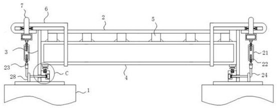
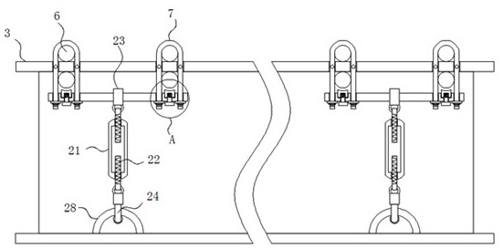
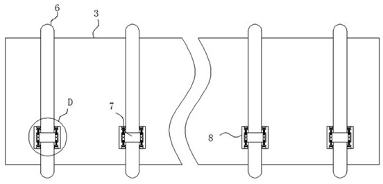
[0032] The invention provides a suspended floor structure, such as Figure 1-4 As shown, it includes several core tubes 1 and a floor body 2, the several core tubes 1 are arranged in two rows, and the top of each row of core tubes 1 is fixedly connected with the same I-shaped steel beam 3, the floor The surface body 2 is arra...


PUM


Abstract

The invention discloses a suspended floor structure and relates to the technical field of building walls. The suspended floor structure includes several core tubes and a floor body. Several core tubes are arranged in two rows, and the top of each row of core tubes is fixedly connected with the same I-shaped steel beam. The floor body is located in two columns. Between the steel girders, a load-bearing frame is arranged at the bottom of the floor body, and several fixing pieces are arranged on the load-bearing frame and the bottom of the floor body. The present invention is equipped with a locking device, which is beneficial to lock and fix the hanging steel bars at the top and bottom of the I-shaped steel beam through the U-shaped lock, and lock and fix the two U-shaped locks at the same time through the locking rod. Prevent the hanging steel bar from falling off, so as to ensure the firmness between the hanging steel bar and the I-beam.

Description

technical field [0001] The invention belongs to the technical field of building walls, in particular to a suspended floor structure. Background technique [0002] The suspended structure is a new structural system formed by using the core tube, rigid frame, arch, etc. as the vertical load-bearing structure, and all floors are firmly hung on the above-mentioned load-bearing structure through steel wire bundles and slings. [0003] At present, the traditional suspension load-bearing is relatively concentrated, all of which are concentrated on the suspension steel bars, and the suspension steel bars are generally fixed to the I-beams by bending. The firmness of this fixing method depends entirely on the strength of the suspension steel bars. When in use, it is easy to cause the deformation of the suspension steel bar, causing the position where the suspension steel bar contacts the I-beam to fall off, resulting in insufficient firmness and safety of the floor suspension. Bindi...

Claims


Application Information

Patent Timeline
Patent Type & Authority Patents(China)
IPC IPC(8): E04B5/02E04B5/10
CPCE04B5/02E04B5/023E04B5/10
Inventor 陈香
Owner 广东洋艺建设有限公司
Learn More